Final Project Milestone #2: Liang

Uncategorized — lianghe @ 11:06 pm

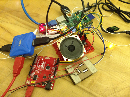
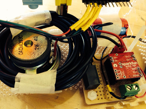
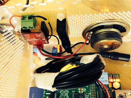
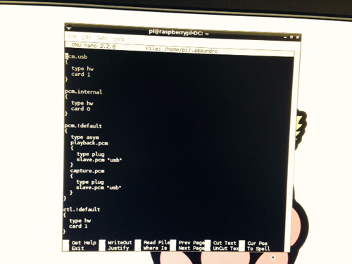
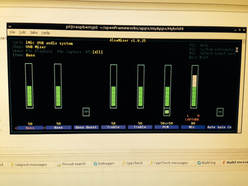
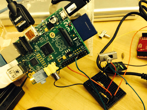
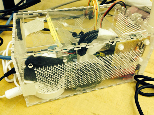
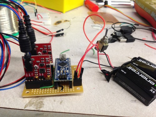
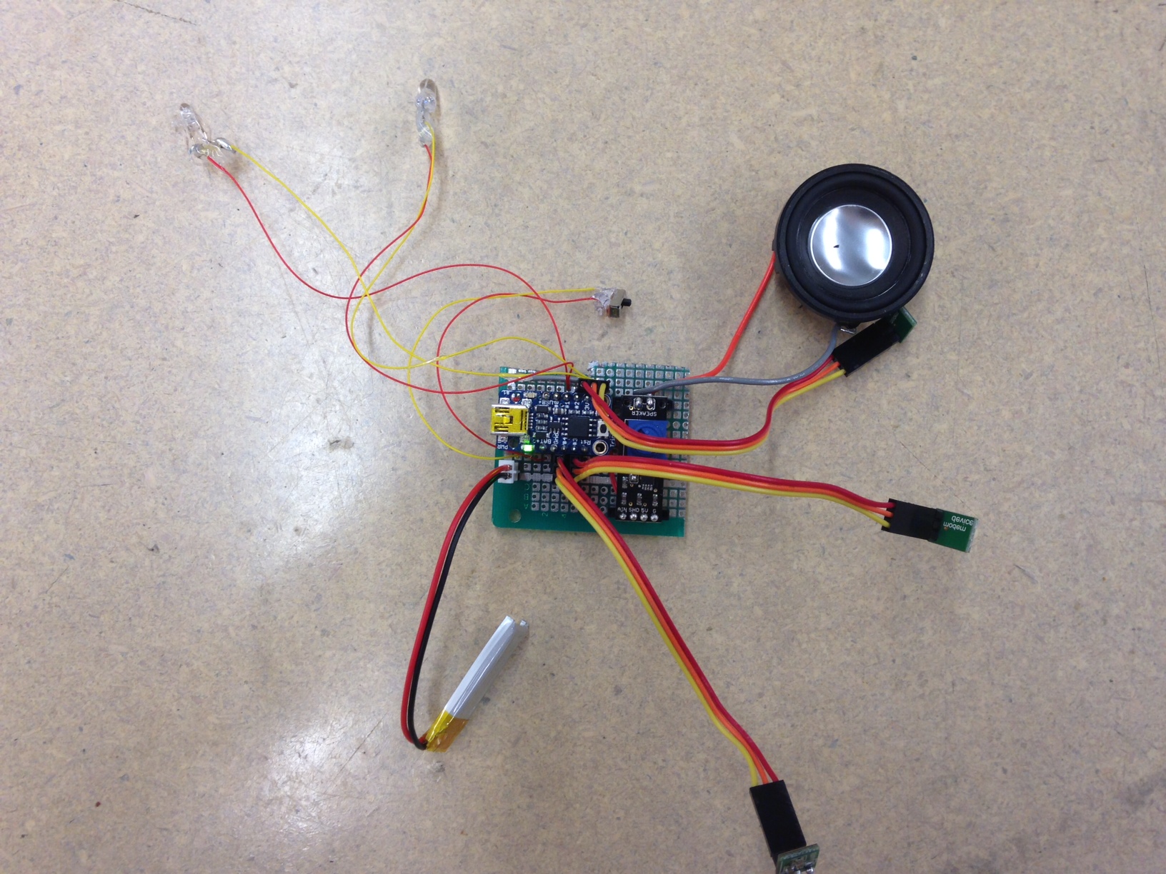
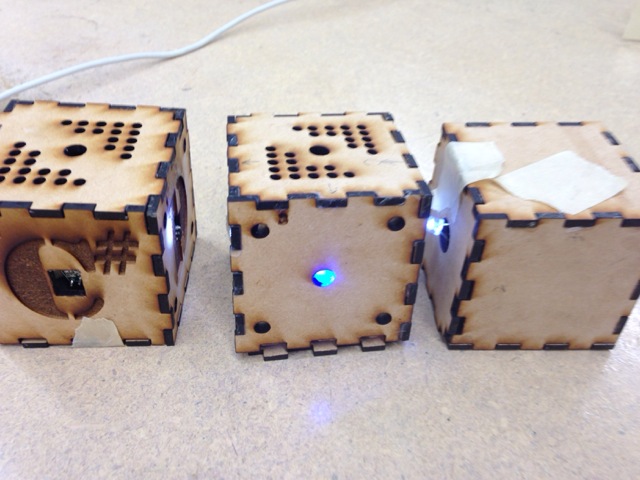
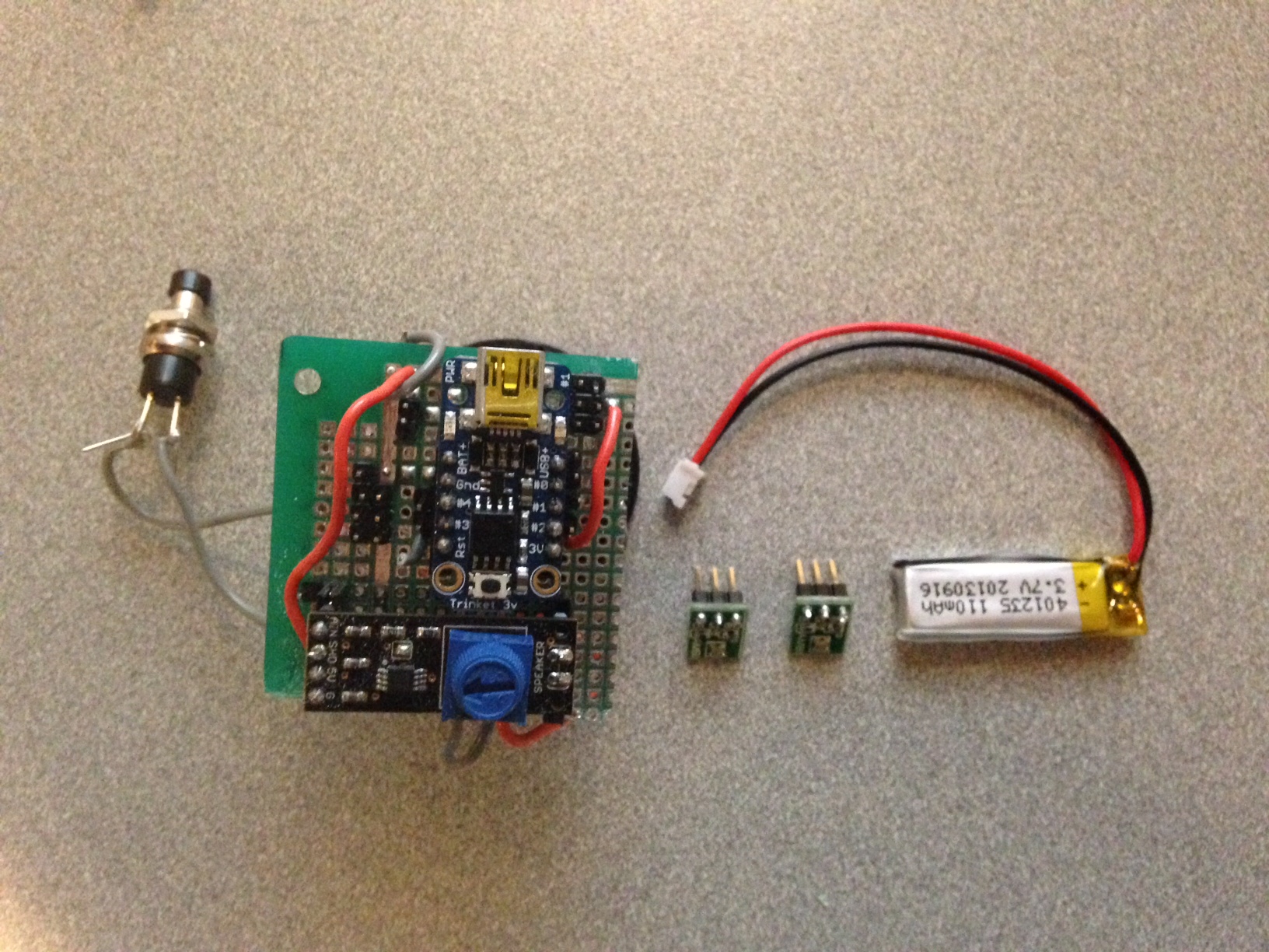
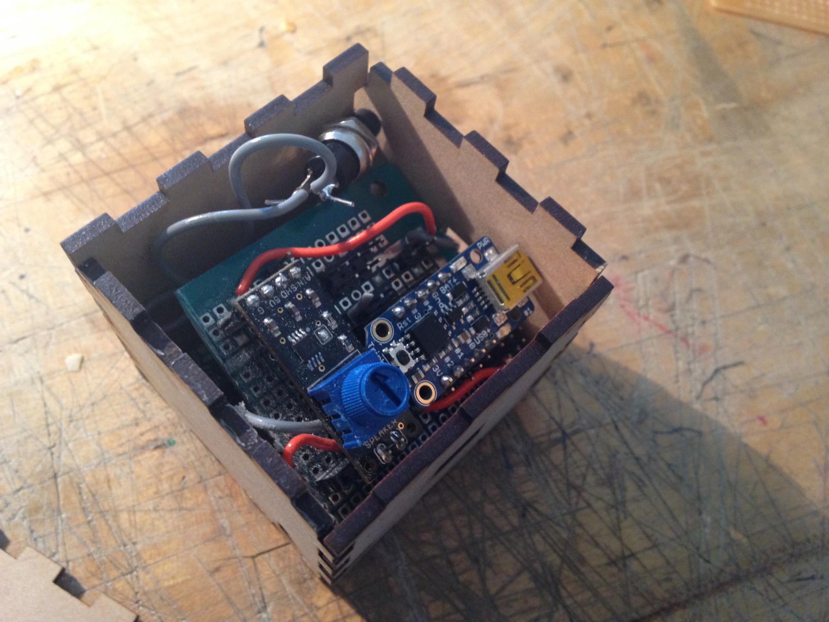
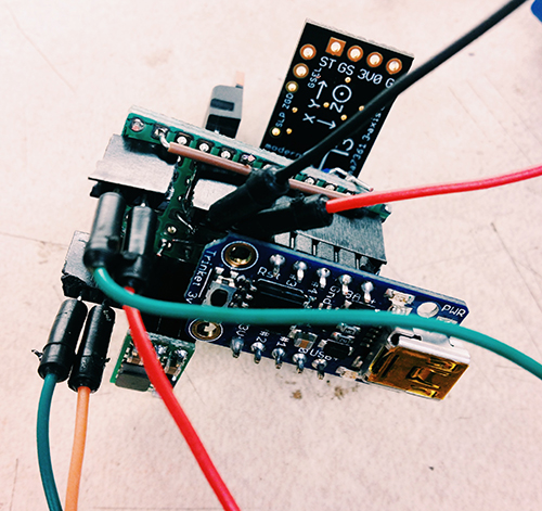
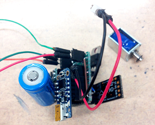
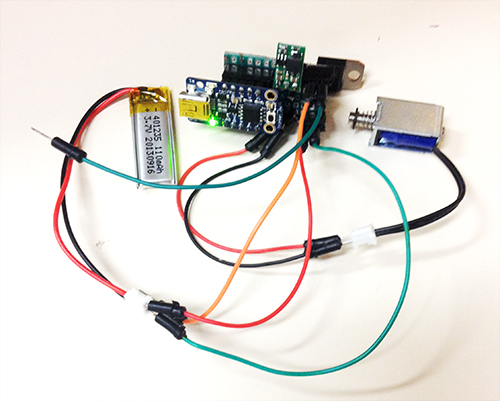
According to design critique from three guests, I rethought the scenarios and target user group. Instead of making tempos, I believe Tapo could produce more for users, for example, rhythms. Yes, with different cups and different resonance, it could generate various rhythms. Imagine multiple users play together, it would be a playful and generic environment for participants to make original rhythms with very original sounds and tempos. As for the target users, I think they depend on the situations where Tapo could fit in. For educational goals, it could be applied in a classroom, teaching students basic process of making rhythms and the connection between the sound and the physical properties of the cup. If it is set up in an public space, it encourages people to play and enjoy the process of making rhythm. So I believe it has great potential in people’s everyday activities. Based on the circuit I built I set up one prototype (actually two prototypes and the first one failed) to test if it runs correctly. Below images show how the prototype looks. Besides testing all components on the board, I also test batteries. In the board I set two separate interfaces for batteries which supply power for the trinket board and the extra solenoid individually. However, test demonstrated that only one battery worked well with all parts. Therefore, I finally selected one small LiPo as the only one power supply.

Processed with VSCOcam with c1 preset milestone_2_2 milestone_2_3

Another work is about gesture detection and recognition. At the beginning I took a complicated process to recognise user’s gesture. The entire solution is shown in the below diagram. The basic idea: The data of X-axis, Y-axis and Z-axis from accelerometer are sent to the controller board. Everytime set a window for data set (it has to be 2^n, I give it 128). When the window is full, calculate these data to get mean value of each axis, entropy value of each axis, energy value of each axis, and correlation value of each two axises (more details about formula and principles please refer to Ling’s paper). Store the result in the form of arff file. Then in Weka import this file and use J48 algorithm to train a decision tree. There are two parts in gesture recognition: gesture recognition model training and test. With different user’s gesture data and above process I could make a decision tree. More tester’s data makes it more robust and accuracy. Then when recognising one gesture, it follows above process but not produces arff file, instead, directly process data and send the result to the trained decision tree, and the classification tells the category of the gesture. I finished a Processing application to visualise the data received from the accelerometer and distinguished four gestures: pick-up, shake, stir counter clockwise, and stir clockwise. I used pick-up gesture to trigger the entire system. Shake gesture can be used to generate random predefined rhythms. Stir counter clockwise means slow down the speed of rhythms. Stir clockwise means speed up rhythms. Below shows the data variation of each axis in different gestures.
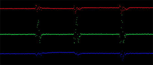
GESTURE-1

Pick-up gesture

GESTURE-2

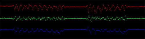
Stir counter clockwise gesture

GESTURE-3

Stir clockwise gesture
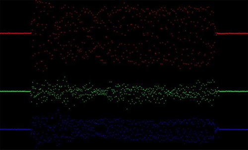
GESTURE-4

Shake gesture

With this method it has one several limitations: a) it needs triggers to start and terminate the gesture detection process; b) two types of stir gestures are not well distinguished; c) since it collects a large number of data it causes delay. In addition, the mapping between the stir gestures and the control of speed of rhythms is weird and not natural. So I adapted another much simple and direct way to test gestures. Since user’s interaction with cups just lasts at most a few seconds, I used 40 data (every 50ms receiving X, Y, Z data) to detect only two gestures: shake and pick-up. The mapping remains the same. The device would be mounted on the cup, so I tried to monitor the data of the axis which is perpendicular to the ground. If the value reaches the threshold that I set, and the other two axises remain stable, it will be regarded as pick-up gesture. To simplify the process, the other conditions are considered as shake gestures. The only problem goes to what kind of interaction and input should exist in this context?

Here is a short demo of gesture recognition:

Final Project Milestone 2 – Ding Xu

Audio,Final Project,Laser Cutter,OpenCV — Ding Xu @ 11:05 pm

In my second milestone. I finished the following stuff:

1. sound output amplification circuit. I first used a breadboard to test the audio output circuit using an amplifier connecting a speaker with a switch to augment the output sound and then  finished soldering a protoboard.

photo_2

photo_7 (2)

photo_8 (2)

2. Sound capture device: a mic with a pre-amp connecting an usb audio card was used for sound input. However, it spent me a lot of  time to configure the parameters in the Raspberrry Pi to make it work. I referred to several blog posts in the website to get asoundrc and asound.conf file well set for audio card select and alsa mixer for control. A arecord and aplay command were used to test the recording in linux. Then I revised an addon of OF ofxLibsndFileRecorder to achieve recording. However, from the testing result, the system is not very robust, sometimes the audio input will fail and sometimes the play speed will much faster than recording speed, accompanying much noise.

photo_11照片2

alsamixer

3. GPIO test: in order to test control the audio input and output with  switch and button. I first used a breadboard connecting a switch with a pull-up or pull down resister as the recording/play control.

photo_22

4. Case building: a transparent case using laser cut was built.

photo(1)

5. Simulink test: I searched that simulink recently supported the raspberry Pi with several well developed modules. So I tried to install an image of Simulink and run some simple demos with that platform. I also tested the GPIO control for triggering the switch between two sine wave generator in Simulink.

gpio1

Final Project Milestone 2 – Ziyun Peng

Assignment,Final Project — ziyunpeng @ 10:56 pm

My second milestone is to make a stable and ready to use system.

Mask
After several tries, I finally got to decide on where the sensing points should be on the face and replaced the electrodes with conductive fabrics following this tutorial by the sensor kit provider. It took me couple of amazon trips to find the right sized snap button and finally got the right ones from Lo Ann. The right size should be 7/16 inches (1.1cm) as is shown in the picture below, in case any of you would need it in the future.

2013-11-22 22.58.06

mask

Center Board
Since there won’t be any change in the circuit, it’s time to solder! What you can see on the board is two muscle sensor breakout, and Arduino Nano and two 9V batteries. The wires coming out will be connected to the buttons on the mask for getting data on the face.

2013-11-22 21.37.16

Final Project Milestone 2 – Mauricio Contreras

Assignment,Final Project,Robotics,Submission,Technique — mauricio.contreras @ 10:02 pm

Log

My second milestone was about simulating the motion of a robotic arm within the software workflow that had been explored in the first milestone (Rhino + Grasshopper + HAL). Upon getting acquainted with the capabilities of these pieces of softwares and understanding more about the possible constraints and needs of the instrument, I realized that REAL TIME driving of the robotic arm was a major requirement. Just imagine sculpting with your arm moving with a few seconds lag after your movement intention and you’ll see why. The software workflow described above is great for offline materialization of 3D designs, but not necessarily for real time control. Even though feasible, people from the lab commented about possible lag issues, which made me want to try out the real motion of the robot, even with simple commands, as soon as possible. I found procuring the tools to run in my own machine rather difficult: All of them are Windows only, so at first I got a virtual machine from Ali Momeni with everything preloaded, but it ran excruciatingly slow (even when I changed my computer to the latest Macbook Pro). Then I tried creating my own virtual machine from scratch, and installed Rhino and Grasshopper with success. Yet HAL’s developer webpage was down and I had problems procuring tutorial training for it. When I asked for help with this, people recommended to learn the former 2 tools first and then use HAL. This seemed reasonable but I was under time constraints (by choice) to test the robots motion as soon as possible with a configuration that would generate the least lag, and evaluate if that optimal setup would prove to be responsive enough to match the target application of the instrument, which is sculpting.

Early motion tests

I then turned to writing my own RAPID code, and quickly was able to generate a routine to move the head of the robot in a square in the air, as shown in the following video.

The routine was based on offsetting the current location by steps in each axis, but also waiting for a digital input state before each small step. Since the robot accepts 24 V digital inputs, I would have had to use a power source or do a conversion circuit from the standard micro controllers 5/3.3 V outputs. That is not difficult but I assumed that the DI of the robots had pull down resistors and just made it wait for DI=0 before each motion. Since the shape was completed that thesis was proven. Also, the motion seemed “cut”, as if doing start-pause-restart in every step, as opposed to a seamlessly continual motion that would have occurred either if the lag on processing the digital input was very low or depending on motion configuration of the robot (i.e. there may be other motion commands that would output less of a “cut” motion). I removed the wait for DI statements with no appreciable effect, hence the motion commands were the issue. To see the effect of this when driving the robot with gestures, and based on previous code for motion (FUTURE CNC LINK), I started writing a TCP/IP socket based client (Android smartphone) – server (robot controller) application, which will be outlined in the next milestone posting.

Assessment

Up to this milestone, just getting access to the robots themselves and being able to move them in a hardcoded fashion I consider a success by itself, yet it is clear that new, unforeseen difficulties have appeared.

Final Project Milestone 2 – Haochuan Liu

Assignment,Audio,Final Project — haochuan @ 7:37 pm

For my milestone 2, I have did a lot of experiments of audio effects in puredata. Besides very simple and common effects (gain, tremolo, distortion, delay, wah-wah) I made in milestone 1, here are the tests and demos I made for these new effects with my guitar.

Test 1: Jazz lead guitar

  • Original audio


  • Bass Synth


  • Falling Star


  • Phaser


  • Reverb


  • Ring Modulation


  • Slow Vibrato


  • Magic Delay


  • Violin


  • Vocoder


Test 2: Acoustic guitar

  • Original audio


  • Bass Synth


  • Falling Star


  • Phaser


  • Reverb


  • Ring Modulation


  • Slow Vibrato


  • Magic Delay


  • Violin


  • Vocoder


Test 3: Guitar single notes

  • Original audio


  • Bass Synth


  • Falling Star


  • Magic Delay


  • Vocoder


Final Project Milestone 3 – Patra Virasathienpornkul

Assignment,Final Project — Patt @ 7:00 pm

My third milestone is to be able to make all the hardwares and softwares talk to each other properly, and have something interesting displayed on the screen. By this time, I am able to accomplish the task, sending the pen stroke data from Processing to 4D Systems through serial communication and have it displayed on the screen smoothly. I got a simple animation interacting with the pen strokes – a prove of concept that everything finally works together. Now, it’s time to make something interesting.

Bouncing Ball from Patt Vira


Final Project Milestone 2 – Patra Virasathienpornkul

Assignment,Final Project — Patt @ 6:52 pm

My original second milestone was to use computer vision as an alternate way to track the pen strokes. However, it took me longer to figure out how to send serial data from Processing to 4D Systems workshop, and how to draw properly on the screen. Therefore, the second week was spent mostly to figure out these problems.

I finally solved the problem from the first milestone, and was able to clear the screen after each draw function. The first video below shows a ball bouncing against two pre-drawn rectangular boundaries. The second one shows a real-time pen strokes being sent from the tablet to Processing to 4D Systems to the display.

Ball Bouncing Against Boundaries from Patt Vira on Vimeo.

Line Drawing from Patt Vira on Vimeo.

I found out from working more with the display that it unfortunately cannot handle heavy libraries, specifically box2D. Consequently, as a proof of concept, my goal is to draw some simple interaction. My next step is to be able to draw the lines from the Wacom tablet, and have the ball interacting with the these lines instead of the rectangular boundaries.


Final Presentation – Sean Lee

Assignment,Final Project — Sean @ 2:50 am

Finally, I built the final prototyping of the device for interactive music listening.

IMG_5747

IMG_5752


And, here is the manual for this device.

HP-Poster-nov-20


The difference between Milestone 3 and final one are that smaller circuit size and form which is more fit-table to wear. In the sound effect and feedback side, I wanted to bring more interactive situation with such as [Bonk~] and beat detector. However, the result brings too much editing to the original music, so I didn’t add to the final show.


Final Project Milestone#3—Wanfang Diao

Assignment,Final Project — Wanfang Diao @ 4:22 pm

I developed the cubes further by adding leds outputs which can gave the cubes ability to trigger one by one. I tried to improve the richness of the sound effect by using PWM, but meet problem of control the pitch of the sound.

Instead of  just copying more cubes, I add more function when create more cubes just like use slide/rotary potentiometers to control the speed and the pitch of the notes.

照片 6 照片 8 照片 9

Music cubes from Wanfang Diao on Vimeo.
Note cubes from Wanfang Diao on Vimeo.

Note Cubes from Wanfang Diao on Vimeo.

Final Project Milestone#2—Wanfang Diao

Assignment,Final Project — Wanfang Diao @ 3:57 pm

In this milestone 2, I finished soldering electronic circuits by using micro-controller, audio amplifier and photosensors. I programed the micro-controller to read the analog input from photo sensors and trigger the speaker to make a note.

After that, I made  a hardboard box to fit the circuits.  So the first version cube has been created.

What’s more I also find a wooden plate for the mechanical part.

照片 11照片 1

照片 2

« Previous PageNext Page »
This work is licensed under a Creative Commons Attribution-Noncommercial-Share Alike 3.0 Unported License.
(c) 2025 Hybrid Instrument Building 2014 | powered by WordPress with Barecity