Final Project: Ziyun Peng

Assignment,Final Project,Uncategorized — ziyunpeng @ 4:16 pm


FACE  YOGA

FACE_YOGA


Idea

There’s something interesting about the unattractiveness that one goes through on the path of pursuing beauty. You put on the facial mask to moisturize and tone up your skin while it makes you look like a ghost. You do face yoga exercises in order to get rid of some certain lines on your face but at the mean time you’ll have to many awkward faces which you definitely wouldn’t want others to see. The Face Yoga Game aims at amplifying the funniness and the paradox of beauty by making a game using one’s face.


Face Yoga Game from kaikai on Vimeo.

Setup

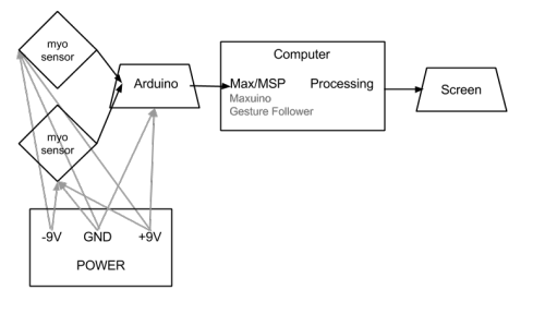
schematic


setup

Learnings

– Machine learning tools: Gesture Follower by IRCAM

This is a very handy tool and very easy to use. There’re more features worth digging into and playing with in the future such as channel weighing and expected speed, etc. I’m glad that got to apply some basics of machine learning in this project and I’m certain that it’ll be helpful for my future projects too.

– Conductive fabrics

This is another thing that I’ve had interest in but never had an excuse to play with. In this project the disappointment is that I had to apply water to the fabrics every time I want to use it but that might be a special case for the myoelectric sensor that I was using. And the performance was not as good with the medical electrodes, possibly due to the touching surface, and since it’s fabric (non-sticky), it moves around while you’re using it.

Obstacles & Potential Improvements

– Unstable performance with the sensors

Although part of this project is to experiment with the possibilities not to use computer vision to detect facial movements, given the fact that the performance wasn’t as good as had been expected, using combination of the both might be the better solution for the future use. One possible alternative I’ve been imagining is that I can use a transparent mask instead of the current one I’m using so that people can see their facial expressions through that and on which I can stick on some color mark points for the computer vision to track with. Although better lightings would be required, vanity lights still stands for this setting.

– User experience and calibration

My ultimate goal is to let everyone involved in the fun, however, opening to all people to play meaning the gestures that I trained myself before hand may not work for everyone, and this was proved on the show day. I was suggested to do a calibration every time at the start of the game play which I think is a very good idea.

– Vanity light bar


Final Project: Conversus Vitra – Can Ozbay

Uncategorized — Can Ozbay @ 4:15 pm

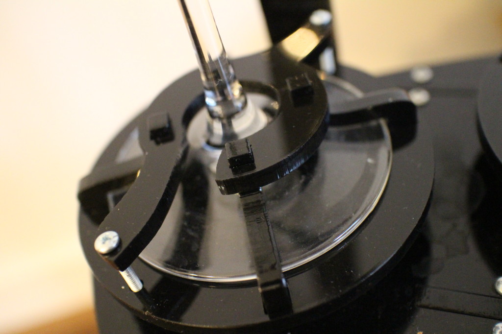
IMG_1952

First I had to find a way to fix the glasses better onto the spinners, and I designed a small screw-cap-lock mechanism to keep them in position.

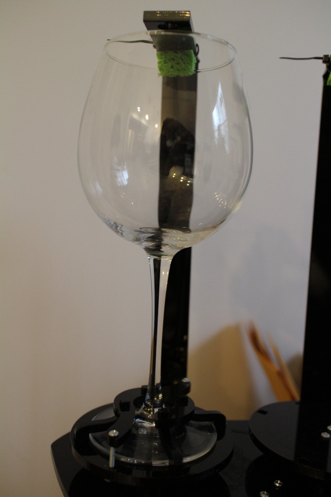
IMG_1953

I’ve reduced the number of pipes, and now there’s only one, both for sucking and pumping.

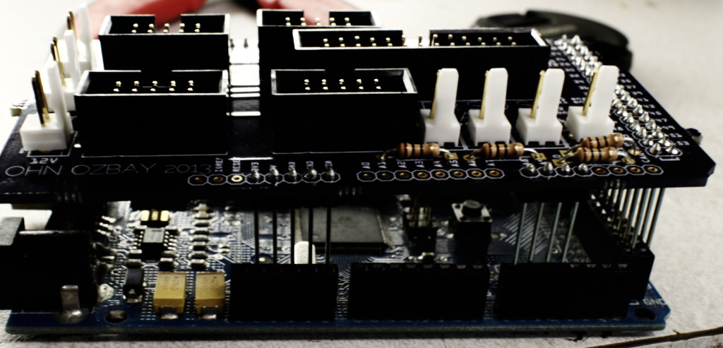
IMG_1954

Finally, my custom made Arduino Due shields came from fabrication, and I’m now cable-free.

IMG_1955 IMG_1956

IMG_1960


Final Project(revised): JaeWook Lee

Uncategorized — jwleeart @ 9:20 pm

IMG_7026

IMG_7029

Ideasthesia
video, 1:56″
2013
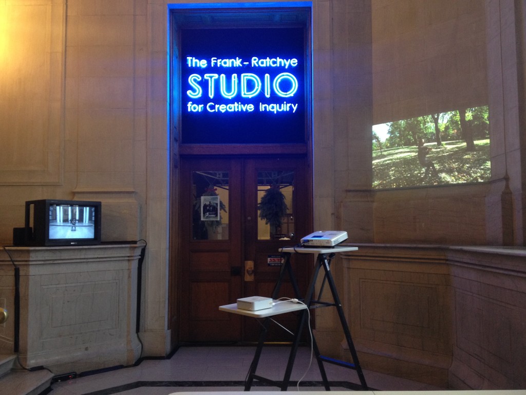
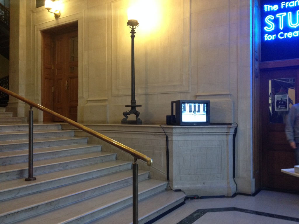
The word “ideasthesia” is a phenomenon in which the activation of ideas evokes perception-like experiences. The term is etymologically derived from the ancient Greek verb idea (idea) and aisthesis (sensation), referring to “sensing concepts.” The project explores how we sense things without actual stimuli, but through the intensive imagination and association in both visual and auditory levels. It is composed of two video works in which a cellist plays the cello without the actual instrument, meaning “air cello” by using her imagination. It was installed in the form of video installation in front of The Studio For Creative Inquiry in CFA.

Ideasthesia from JaeWook Lee on Vimeo.

Final Project: Jake Marsico

Final Project,Submission,Uncategorized — jmarsico @ 11:45 pm

The final deliverable of these two instruments (video portrait register and reactive video sequencer) was a series of two installations on the CMU campus.

 Learnings:

The version  shown in both installations had major flaws.  The installation was meant to show a range of clips that varied in emotion and flowed seamlessly together. Because I shot the footage before completing the software, it wasn’t clear exactly what I needed from the actor (exact time of each clip, precision of face registration, number of clips for each emotion).  After finishing the playback software, it became clear that the footage on hand didn’t work as well as it could.  Most importantly, the majority of the clips lasted for more than 9 seconds. In order to really nail the fluid transitions, I had to play each clip foward and then in reverse, so as to ensure each clip finished in the same position it started. To do that with each 9 second clip would have meant that each clip would have lasted a total of 18 seconds (9 forward, 9 backwards). These 18 second clips would eliminate any responsiveness to movements of viewers.

As a result, I chose to only use the first quarter of each clip and play that forward and back. Although this made the program more responsive to viewers, it cut off the majority of the subject’s motions and emotions, rendering the entire piece almost emotionless.

Another major flaw is that the transitions between clips very noticeable as a result of imperfect face registrations. In hindsight, it would require an actor or actress with extreme dedication and patience to perfectly register their face at the beginning of each clip. It might also require some sort of physical body registering hardware. A guest critic suggested that a better solution might be to pair the current face-registration tool with a face-tracking and frame re-alignment application in post production.

If this piece were to be shown outside the classroom, I would want to re-shoot the video with a more explicit “script” and look into building a software face-aligning tool using existing face-tracking tools such as ofxFaceTracker for openFrameworks.

Code:

github.com/jmarsico/Woo/tree/master


Final Project Milestone #2: Liang

Uncategorized — lianghe @ 11:06 pm

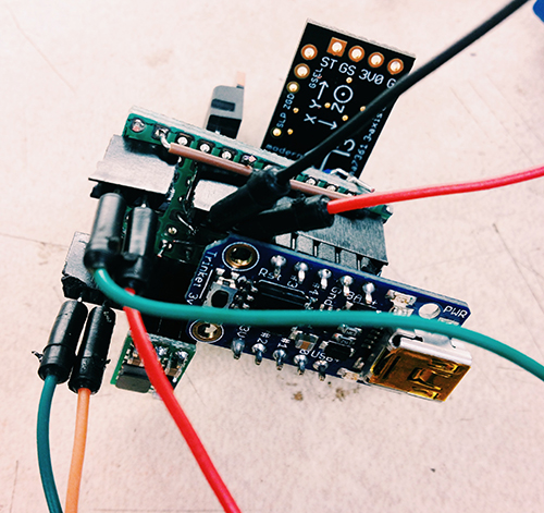
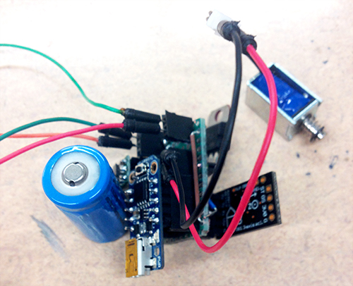
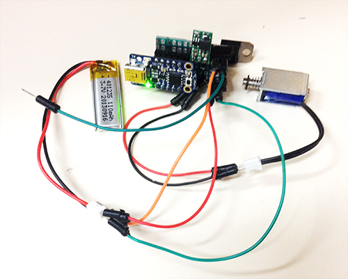
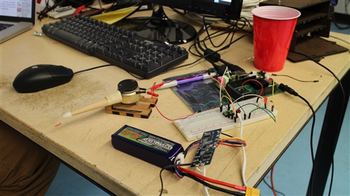
According to design critique from three guests, I rethought the scenarios and target user group. Instead of making tempos, I believe Tapo could produce more for users, for example, rhythms. Yes, with different cups and different resonance, it could generate various rhythms. Imagine multiple users play together, it would be a playful and generic environment for participants to make original rhythms with very original sounds and tempos. As for the target users, I think they depend on the situations where Tapo could fit in. For educational goals, it could be applied in a classroom, teaching students basic process of making rhythms and the connection between the sound and the physical properties of the cup. If it is set up in an public space, it encourages people to play and enjoy the process of making rhythm. So I believe it has great potential in people’s everyday activities. Based on the circuit I built I set up one prototype (actually two prototypes and the first one failed) to test if it runs correctly. Below images show how the prototype looks. Besides testing all components on the board, I also test batteries. In the board I set two separate interfaces for batteries which supply power for the trinket board and the extra solenoid individually. However, test demonstrated that only one battery worked well with all parts. Therefore, I finally selected one small LiPo as the only one power supply.

Processed with VSCOcam with c1 preset milestone_2_2 milestone_2_3

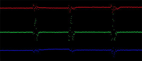
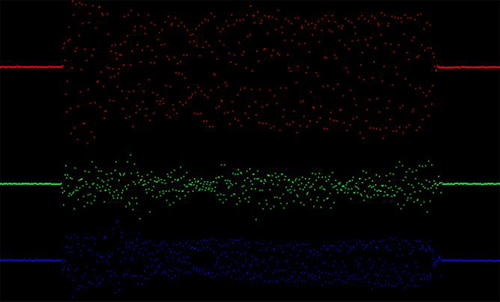
Another work is about gesture detection and recognition. At the beginning I took a complicated process to recognise user’s gesture. The entire solution is shown in the below diagram. The basic idea: The data of X-axis, Y-axis and Z-axis from accelerometer are sent to the controller board. Everytime set a window for data set (it has to be 2^n, I give it 128). When the window is full, calculate these data to get mean value of each axis, entropy value of each axis, energy value of each axis, and correlation value of each two axises (more details about formula and principles please refer to Ling’s paper). Store the result in the form of arff file. Then in Weka import this file and use J48 algorithm to train a decision tree. There are two parts in gesture recognition: gesture recognition model training and test. With different user’s gesture data and above process I could make a decision tree. More tester’s data makes it more robust and accuracy. Then when recognising one gesture, it follows above process but not produces arff file, instead, directly process data and send the result to the trained decision tree, and the classification tells the category of the gesture. I finished a Processing application to visualise the data received from the accelerometer and distinguished four gestures: pick-up, shake, stir counter clockwise, and stir clockwise. I used pick-up gesture to trigger the entire system. Shake gesture can be used to generate random predefined rhythms. Stir counter clockwise means slow down the speed of rhythms. Stir clockwise means speed up rhythms. Below shows the data variation of each axis in different gestures.

GESTURE-1

Pick-up gesture

GESTURE-2

Stir counter clockwise gesture

GESTURE-3

Stir clockwise gesture

GESTURE-4

Shake gesture

With this method it has one several limitations: a) it needs triggers to start and terminate the gesture detection process; b) two types of stir gestures are not well distinguished; c) since it collects a large number of data it causes delay. In addition, the mapping between the stir gestures and the control of speed of rhythms is weird and not natural. So I adapted another much simple and direct way to test gestures. Since user’s interaction with cups just lasts at most a few seconds, I used 40 data (every 50ms receiving X, Y, Z data) to detect only two gestures: shake and pick-up. The mapping remains the same. The device would be mounted on the cup, so I tried to monitor the data of the axis which is perpendicular to the ground. If the value reaches the threshold that I set, and the other two axises remain stable, it will be regarded as pick-up gesture. To simplify the process, the other conditions are considered as shake gestures. The only problem goes to what kind of interaction and input should exist in this context?

Here is a short demo of gesture recognition:

Final Project Presentation: Ding

Uncategorized — Ding Xu @ 5:41 pm

Final Project – JaeWook Lee

Assignment,Final Project,Uncategorized — jwleeart @ 10:16 pm

Ideasthesia_installation view


Ideasthesia_installation view
Ideasthesia_installation view
Instrument: “Disarm” by Pedro Reyes (2013)

Uncategorized — David Lu @ 5:10 pm

More…

Final Project Milestone 2 – Robert Kotcher, Haris Usmani

Assignment,Description,Hardware,Uncategorized — rkotcher @ 10:44 am

Milestone 1,2 Goals:

Milestone 1: Explore different types of actuators, and the sounds they can produce in different spaces. Determine how we can enhance these sounds in Pure Data.

Milestone 2: Make CAD models for crickets, build proof-of-concepts, and order any additional parts we might need.

Milestone 2 Progress:

The implementation of our milestone 2 goals was carried out in two separate areas. The first involved creating a box that could hold the components necessary for a cricket, and the second part was getting the Udoo to talk to a single actuator. Each of these items are described in detail below, and progress photos are also listed throughout the rest of this post.

Hardware Design of Crickets:
We decided to make a laser cut box to hold all our electronics, and to support the ‘goose-necks’ we plan to use to position and hold the actuators in place along with providing us flexibility. This box is now designed and we have a 2nd prototype of it- there are three compartments: The 1st compartment holds the Udoo, the 2nd houses the 50W x 2 Audio Amp and the 3rd holds the battery and the power/driving circuitry.

The box is strong enough to hold the weight of the goose-necks and the actuators. All sides are ‘interlocking’ except for one. This side allows service of inner electronics, as required.

The top and bottom of the box are cut with a thicker sheet of Masonite, as these would support the box or the actuators. So the plan is to allow this box to be attached to any 1/4 inch 20 bolt holder (like all tripods) so it can attach to whatever support we want. To distribute the weight, we will thread a 1/4 inch 20 into a metal sheer (similar to the template you can see in the diagram) and cut it so as to bind it to the lower side of the box. The top of the box already has space for attaching 4 actuators, as the four holed allow 4 goose-necks to be attached- we wouldn’t use more than 2 for now.

All the hardware required (screws, bolts, nuts) have been ordered.

IMG_0343

Udoo, actuators
Our initial tests with the actuators used simple transistors connected directly to a DC power supply. This week we were able to connect a striker to the Udoo, and control it using a simple PureData software interface to the Udoo’s GPIOs.

Specifically, our striker actuator is connected to a DRV8835 dual motor driver, which uses logical power from the Udoo, and motor power from a battery back. We’ll need two of these motor drivers for each cricket, each of which will control four actuators.

The video below shows our basic setup. The next step is to make the circuitry more robust and portable, so that we can quickly scale to more actuators in week 3.

IMG_0340

Final Project Milestone 2 – Jake Marsico

Assignment,Final Project,Max,Uncategorized — jmarsico @ 1:21 pm

_MG_2036

The Shoot

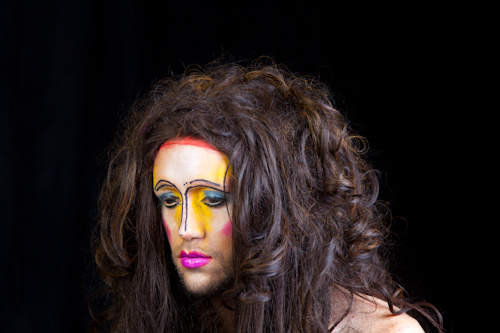
This past weekend I finished the video shoot with The Moon Baby. Over the course of three and a half hours, we shot over 80 clips. A key part of the project was to build a portrait rig that would allow the subject to register her face at the beginning of every clip. The first prototype of this rig consisted of a two way mirror that had registration marks on it. The mirror prototype proved to be inaccurate.

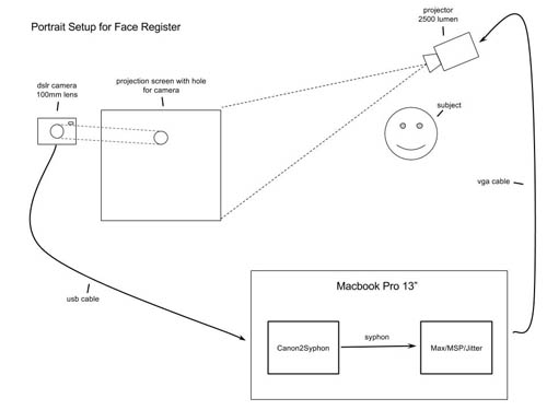
The second prototype, which we used for the shoot, relied on a direct video feed from the video camera, a projector and a projection surface with a hole cut out for the camera to look through.


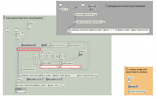
At the center of this rig was a max/msp/jitter patch that overlayed a live feed from the video camera on top of a still “register image”. This way, the subject was able to see her face as the camera saw it, and line up her eyes, nose, mouth and makeup with a constant still image. See an image of the patch below:

max_screenshot


The patch relied on Blair Neal’s Canon2Syphon application, which pulls video from the Canon dslr’s usb cable and places it into a syphon stream.  That stream is then picked up by the max/msp/jitter patch.

Here is a diagram of the entire projection rig:

Woo portrait setup

Soon into the shoot, we realized a flaw with the system: the Canon camera isn’t able to record video to its CF card while its video feed is being sent to the computer.  As a result, we had to unplug the camera after the subject registered her face, record the clip, then plug the camera back in.  We also had to close and reopen Canon2Syphon after each clip was recorded.

SONY DSC

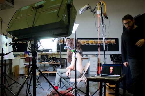
Wide shot of the entire setup.


To light the subject, I used a combination of DMX-controlled fluorescent and LED lights along with several flags, reflectors and diffusers.


Next Page »
This work is licensed under a Creative Commons Attribution-Noncommercial-Share Alike 3.0 Unported License.
(c) 2024 Hybrid Instrument Building 2014 | powered by WordPress with Barecity