Final Project “TAPO”: Liang

TAPO: Speak Rhythms Everywhere

Idea Evolution:

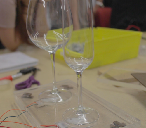
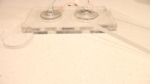
This project comes from the original idea that people can make rhythms through the resonant property and material of cups and interacting with cups. However, as the project progresses, it is more interesting and proper for people to input the rhythms by speaking than do gestures on cups. It also extends the context from cups to any surface because of the fact that each object has resonant property and specific material. So, the final design and function of TAPO have a significant change from the very raw idea. The new story here is:

“Physical objects have resonance property and specific material. Tap object gives different sound feedback and percussion experience. People are used to making rhythms by beating objects. So, why not provide a tangible way not only allowing people to make rhythms with physical objects around she/he, but also enriching the experience by some computational methods. The ultimate goal for this project is that ordinary people can make and play rhythms with everyday objects, even perform a piece of percussion performance.”

Design & Key Features:

TAPO is an autonomous device that generates rhythms according to people’s input (speech, tapping, making noise). TAPO can be placed on different surfaces, like desk, paper, ground, wall, window… With different material and the object’s resonant property, it is able to create different quality of sound. People’s input gives the pattern of rhythm.

System diagram

a) voice, noise, oral rhythm, beat, kick, knock, oral expression… can be the user input

b) using photo resistor to trigger recording

c) get rid of accelerometer, add led to indicate the state of recording and rhythm play
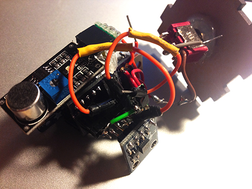
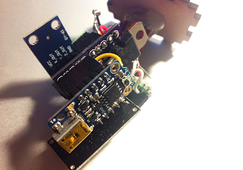
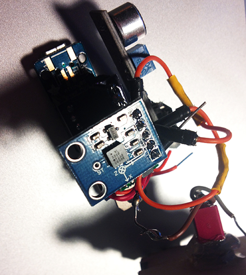
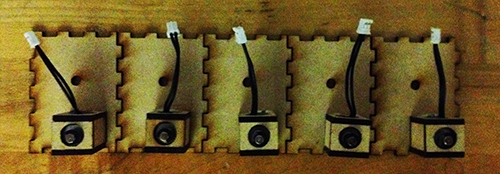
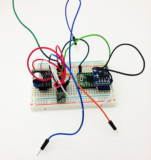
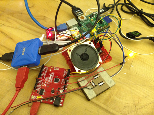
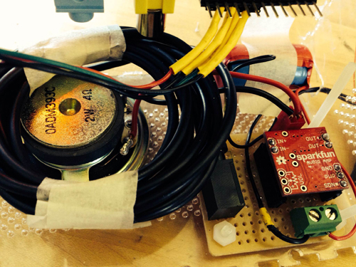
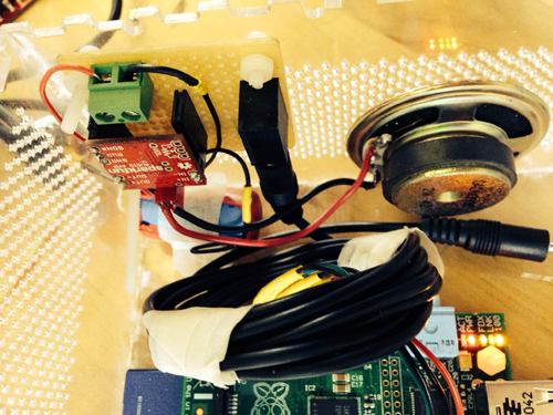
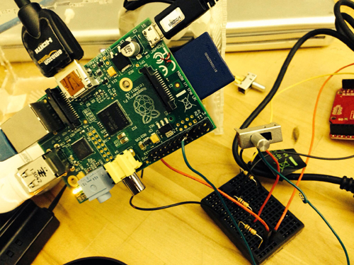
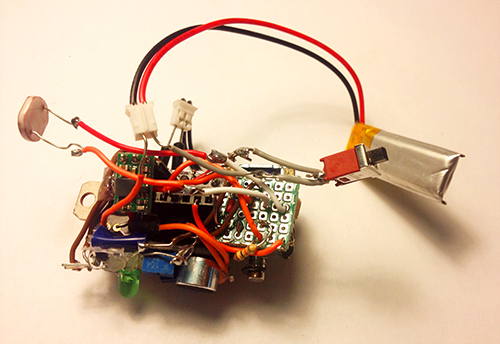
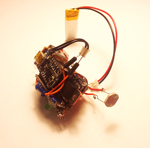
Hardware

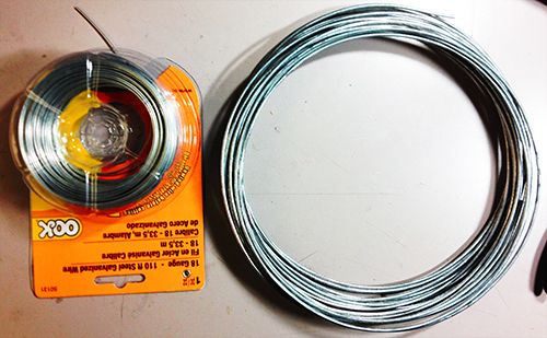
It is composed of several hardware components: a solenoid, a microphone electret, a transistor, a step-up voltage regulator, a Trinket board, a colourful LED, a photocell, a switch and a battery.
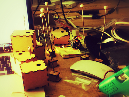
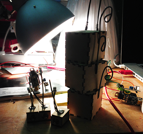
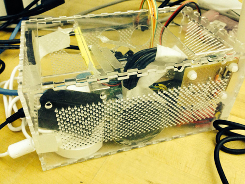
photo1


photo2


Fabrication

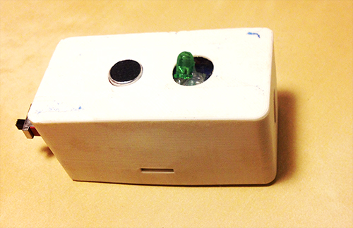
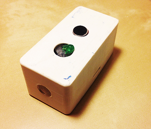
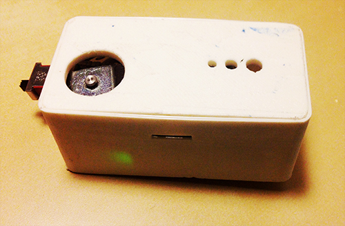
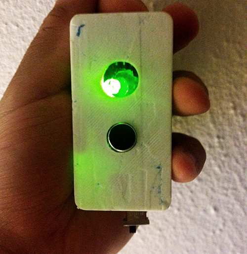
I used 3D printing enclosure to package all parts together. The holes with different sizes on the bottom are used for different usage, people can mount a hook or a suction. With these extra tools, it can be places on any surfaces. The other big hole is used for solenoid to beat the surface. The two holes on the top  side are used to show microphone and LED light separately. On each side, there is a hole for photo resistor and switch.

photo3 photo4

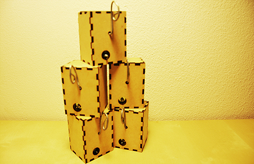
TAPO finally looks like this:

photo6 photo5 photo7 photo8 photo9

Demostration:

Final introduction video:

Conclusion & Future Work:

This project gives me a lot more than technology. I learn about how to design and develop a thing from a very raw idea, and keeping thinking about its value, target users, and possible scenarios in a quick and iterative process. I really enjoy the critique session, even though it is tough and sometimes makes me feel disappointed. The positive suggestions are always right and lead me to a high level and more correct direction. I realise my problems on motivation, design, and stroytelling from these communications. Fortunately, it gets much more reasonable from design thinking to value demonstration. I feel better when I find something more valuable and reasonable comes up in my mind. It also teaches me the significance of demonstrating my work when it is hard to describe and explain. In the public show on Dec. 6th, I found people would like to play with TAPO and try different inputs, they are curious about what kind of rhythm TAPO could generate. In the following weeks, I will refine the hardware design and rich the output (some control and digital outputs).

Acknowledge:

I would like to thank very much Ali Momeni for his advices and support on technology and idea development, and all the guest reviewers who gave me many constructive suggestions.

Final Project Documentation: The Wobble Box

Assignment,Audio,Final Project,Laser Cutter,Max,Sensors — Tags: , , , — Jake Berntsen @ 5:16 pm

After taking time to consider exactly what I hope to accomplish with my device, the aim of of my project has somewhat shifted. Rather than attempt to build a sound-controller of some kind that includes everything I like about current models while implementing a few improvements, I’ve decided to focus only on the improvements I’d like to see. Specifically, the improvements I’ve been striving for are simplicity and interesting sensors, so I’ve been spending all of my time trying to make small devices with very specific intentions. My first success has been the creation of what I’m calling the “Wobble Box.”

IMG_1522

IMG_1524

Simply stated, the box contains two distance sensors which are each plugged into a Teensy 2.0.  I receive data from the sensors within Max, where I scale it and “normalize” it to remove peaks, making it more friendly to sound modulation.  While running Max, I can open Ableton Live and map certain audio effects to parameters in Max.  Using this technique I assigned the distance from the box to the cutoff of a low-pass filter, as well as a slight frequency modulation and resonance shift.  These are the core elements of the traditional Jamaican/Dubstep sound of a “wobble bass,” hence the name of the box.  While I chose this particular sound, the data from the sensors can be used to control any parameters within Ableton.

IMG_1536

IMG_1535

IMG_1532

Designing this box was a challenge for me because of my limited experience with hardware; soldering the distance sensors to the board was difficult to say the least, and operating a laser-cutter was a first for me.  However, it forced me to learn a lot about the basics of electronics and I now feel confident in my ability to design a better prototype that is smaller, sleeker, and more compatible with similar devices.  I’ve already begun working on a similar box with joysticks, and a third with light sensors.  I plan to make the boxes connectible with magnets.

IMG_1528For my presentation in class, I will be using my device as well as a standard Akai APC40.  The wobble box is not capable or meant to produce its own melodies, but rather change effects on existing melodies.  Because of this, I will be using a live-clip launching method to perform with it, making a secondary piece of hardware necessary.


Final Project Milestone #3: Liang

Final Project,Laser Cutter,Rhino3D,Sensors — lianghe @ 2:23 am

1. My boards arrived!!

After about 12 days, OSH Park fabricated and delivered my boards. Yes, they are fantastic purple and look like exactly what I expect. I soldered and assembled every components together to test the board. Finally, all boards work with all the components but the transistor. I used smaller one instead of TIP 120. For some reason, it could work with Trinket board. So, I used TIP 120 again with my final board.

photo


2. Add Microphone Module!

To solve the problem of gestures and how user interacts with cup and Tapo, I decided to use a microphone to record user’s input (oral rhythm, voice, and even speech). The idea is quite simple: since the electret microphone turns analog voice data into digital signal, I can just make use of the received signal and generate certain beat for a rhythm. That is more reasonable interaction for users and my gestures can be put into two categories: trigger the recording and clear the recorded rhythm. The image below shows the final look of the hardware part, including the PCB board, Trinket board, transistor, step-up voltage regulator, solenoid, accelerometer, electret microphone, and a switch.

photo

photo1


photo2


3. Fabrication!

All parts should be enclosed in a little case. At the beginning I was thinking of 3D printing a case and using magnets to fix the case on the cup. I 3D printed some buckets with magnet to see the magnetic power. It seemed not very well in attracting the whole case. The other thing looks difficult for 3D printing case was that it was not easy to put the entire hardware part in and get it out.

photo copy

Then I focused on laser cutting.  I created a box for each unit and drilled one hole for solenoid, one hole for microphone and a hole for hook. I experienced three versions: the first one left one hole for the wire of solenoid to go through, thereby connecting with the main board. But the solenoid could not be fixed quite well (I used strong steel wire to support it); The second version put the solenoid inside the box and opened a hole on the back facet, so that it could tap the cup it was mounted on, but the thickness of the box avoided the solenoid to touch object outside; In the final version I drilled a hole on the upper plate for the switch, and modified the construction for solenoid.

photo

photo copy


Version 1

photo copy

Version 2

photo copy

Solenoids

DSC_0110 copy1

Version 3

Another thing is the hook. I started with a thick and strong steel wire and resulted in that it could not be bended easily. Then I used a thinner and softer one, so that it could be bended to any shape as the user wished.

photo copy

4. Mesh up codes and test!!

Before program the final unit, I programmed and tested every part individually. The accelerometer and the gestures worked very well, the solenoid worked correctly, and I could record user’s voice by microphone and transferred it to certain pattern of beats. Then the challenge is how to make a right logic for all the things work together.  After several days’ programming, testing, debugging, I meshed up all logics together. The first problem I met was the configuration of Trinket, which led to my code could not be burned to the board. Then the sequence of different module messed up. Since the micro controller processed data and events in a serial sequence, so the gesture data could not be “timely” obtained while the beats of solenoid depended on several delays.

I built a similar circuit, in which my custom PCB was replaced by a breadboard, to test my code. In the test, I hoped to check if my parameters for the interval of every piece of rhythm was proper, if the data number of the gesture set was enough to recognise gestures, if specific operation causes specific events, and most importantly, if the result looked good and reasonable.

Here is the test unit:

photo copy

Here is a short video demo of the test:

Final Project Milestone 2 – Ding Xu

Audio,Final Project,Laser Cutter,OpenCV — Ding Xu @ 11:05 pm

In my second milestone. I finished the following stuff:

1. sound output amplification circuit. I first used a breadboard to test the audio output circuit using an amplifier connecting a speaker with a switch to augment the output sound and then  finished soldering a protoboard.

photo_2

photo_7 (2)

photo_8 (2)

2. Sound capture device: a mic with a pre-amp connecting an usb audio card was used for sound input. However, it spent me a lot of  time to configure the parameters in the Raspberrry Pi to make it work. I referred to several blog posts in the website to get asoundrc and asound.conf file well set for audio card select and alsa mixer for control. A arecord and aplay command were used to test the recording in linux. Then I revised an addon of OF ofxLibsndFileRecorder to achieve recording. However, from the testing result, the system is not very robust, sometimes the audio input will fail and sometimes the play speed will much faster than recording speed, accompanying much noise.

photo_11照片2

alsamixer

3. GPIO test: in order to test control the audio input and output with  switch and button. I first used a breadboard connecting a switch with a pull-up or pull down resister as the recording/play control.

photo_22

4. Case building: a transparent case using laser cut was built.

photo(1)

5. Simulink test: I searched that simulink recently supported the raspberry Pi with several well developed modules. So I tried to install an image of Simulink and run some simple demos with that platform. I also tested the GPIO control for triggering the switch between two sine wave generator in Simulink.

gpio1

Final Project Presentation: Liang

Final Project,Laser Cutter,Sensors — lianghe @ 2:52 am

The final project goes wrong with Pin conflict on Trinket. Since I use Pin #1 to read microphone’s digital data and Pin #2 (Trinket requires “1”, which means A1, instead of “2” in code) to read analog X-axis accelerometer data,  it gets confused when I have to write the same command “PinMode(1, INPUT);” in the code to execute both data read. It leads to the failure of reading microphone and accelerometer at the same time. Annoyingly, I had to use Teensy at the very last minute instead to perform my demo. It was not robust and that good, and very preliminary. I felt sorry for the audience and reviewers that night. However, they gave me a lot of feedback and suggestions on potential revise and development. Here I sum up some key points:

1. My biggest problem is that I attempt to cover many scenarios and applications, which is so generic that confuses audiences and eventually lose its value. It fails to address the major problem it tries to figure out, or the goal for its exist. It throws abstract pictures to audience, leave alone under the situation that it cannot work.

2. The gesture seems weird since the microphone works part the role of the gesture. I would argue that the gesture is kind of the way people feel the liquid in the cup. Honestly, when I design the gesture, I find only one gesture (shake) is meaningful for people.

3. Other formations. No matter what kind of stuff I want to create and make, it should respect my motivation and its goal. So, again it goes back to “Point #1”.

I agree with most of the comments in the critique and they drive me recall my original motivation: I know cup has resonance with liquid, cup has material, people use cup, and it can be an instrument to perform music. In the past weeks, I continue to do some research how to make use of these characters and what kind of music it can generate. Here I have some answers: it can generate beats, then rhythm, so it can perform some kind of percussion performance. Besides cups, other objects also have resonance property. When I look back at these, I narrow down my scenario for Tapo and come up with a new but iterative design and development solution.

Redefine the story for TAPO

Physical objects have resonance property and specific material. Tap object gives different sound feedback and percussion experience. People are used to making rhythms by beating objects. So, why not provide a tangible way not only allowing people to make rhythms with physical objects around she/he, but also enriching the experience by some computational methods. The ultimate goal for this project is that ordinary people can make and play rhythms with everyday objects, even perform a piece of percussion performance.

Final Project Proposal – Can Ozbay


glassPresent

www.glissglass.com


Final Project Proposal – Wanfang Diao

Assignment 2: “GlasSpinner” by Can Ozbay & Patra Virasathienpornkul (2013)

Assignment,Laser Cutter,Submission,Technique — Can Ozbay @ 6:41 pm

GlasSpinner is an instrument, where a player stations his fingers on the wine glasses, touches and the instrument produces sound while the glasses spin underneath.

In the past I’ve worked with wine glasses, and I loved their sound. Just to be clear, if you don’t know what I’m talking about – when you rub your fingers, they make beautiful sounds! But this is a hard process. You have to hold the glass, rub your finger with a constant spin, and it’s a tricky thing to achieve. So I’ve came up with the idea of making wine glasses spin automatically! Me and Patt teamed up, and together we’ve designed an acrylic base that holds them together. Instead of rubbing your finger around the glass, the motor drives the two bases that hold and spin the glasses, allowing you to place your finger stationary. The first prototype worked, but it was bulky and unstable. We were able to achieve a decent sound from the first glass, but the spin rate of the second glass wasn’t enough, because of the design of the spinners.

After the first working prototype, we decided to design a new body, focusing on stability and simplicity. This time, we’ve made it very modular(ikea-esque) for ease of carrying and use. We chose different sized transparent acrylic as the main material, and lasercut all the parts. There were some problems due to the accuracy of the laser cutter, that prevented the glass holder to spin smoothly. However, we managed to fix it by sanding the holes to leave some room between the circles and the holes.

Here are some photos of the old prototypes :


old protoype


glassPresent

This work is licensed under a Creative Commons Attribution-Noncommercial-Share Alike 3.0 Unported License.
(c) 2025 Hybrid Instrument Building 2014 | powered by WordPress with Barecity