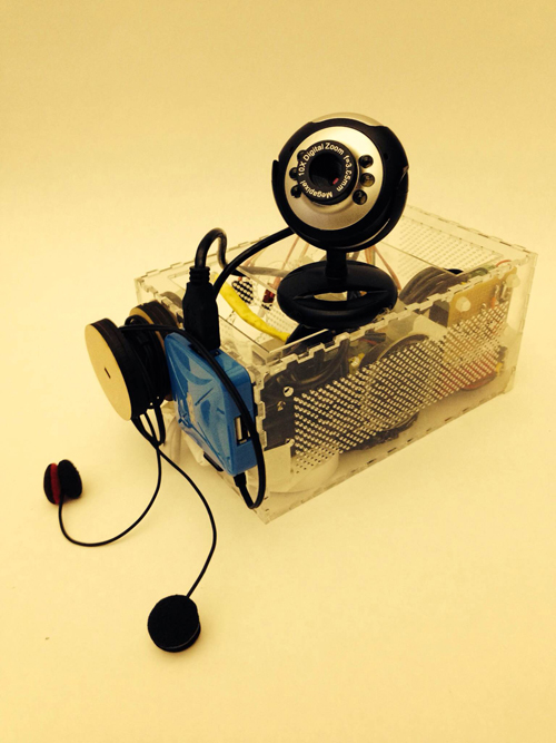
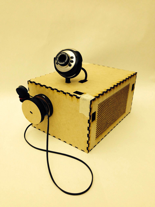
Final Project “TAPO”: Liang

TAPO: Speak Rhythms Everywhere

Idea Evolution:

This project comes from the original idea that people can make rhythms through the resonant property and material of cups and interacting with cups. However, as the project progresses, it is more interesting and proper for people to input the rhythms by speaking than do gestures on cups. It also extends the context from cups to any surface because of the fact that each object has resonant property and specific material. So, the final design and function of TAPO have a significant change from the very raw idea. The new story here is:

“Physical objects have resonance property and specific material. Tap object gives different sound feedback and percussion experience. People are used to making rhythms by beating objects. So, why not provide a tangible way not only allowing people to make rhythms with physical objects around she/he, but also enriching the experience by some computational methods. The ultimate goal for this project is that ordinary people can make and play rhythms with everyday objects, even perform a piece of percussion performance.”

Design & Key Features:

TAPO is an autonomous device that generates rhythms according to people’s input (speech, tapping, making noise). TAPO can be placed on different surfaces, like desk, paper, ground, wall, window… With different material and the object’s resonant property, it is able to create different quality of sound. People’s input gives the pattern of rhythm.

System diagram

a) voice, noise, oral rhythm, beat, kick, knock, oral expression… can be the user input

b) using photo resistor to trigger recording

c) get rid of accelerometer, add led to indicate the state of recording and rhythm play

Hardware

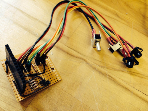
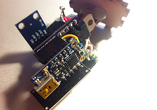
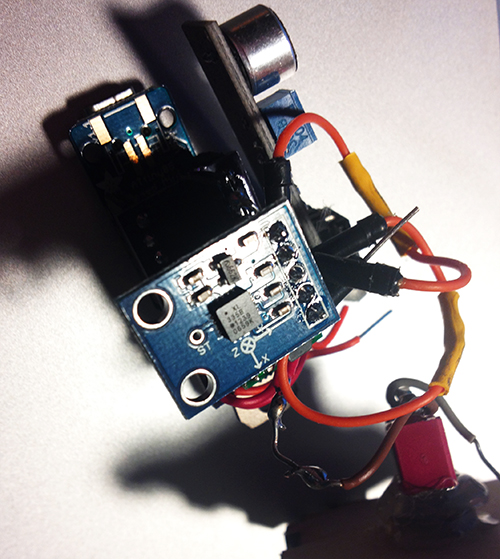
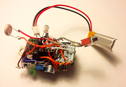
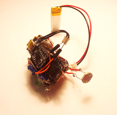
It is composed of several hardware components: a solenoid, a microphone electret, a transistor, a step-up voltage regulator, a Trinket board, a colourful LED, a photocell, a switch and a battery.

photo1


photo2


Fabrication

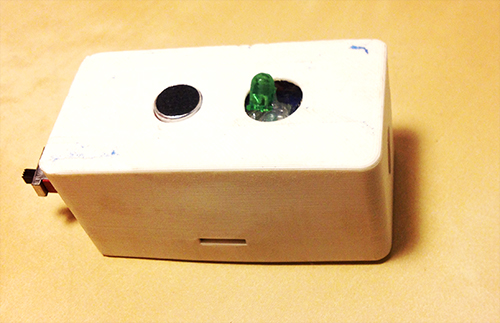
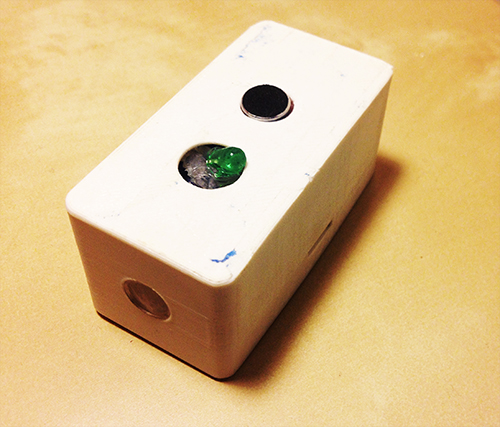
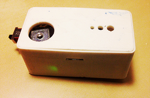
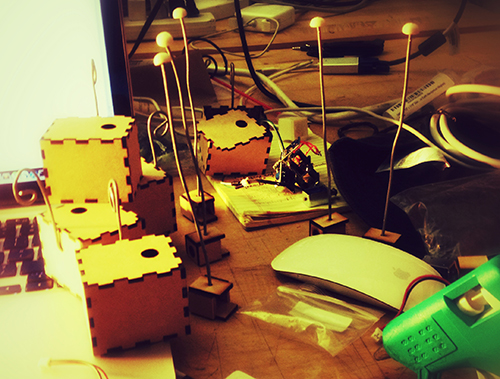
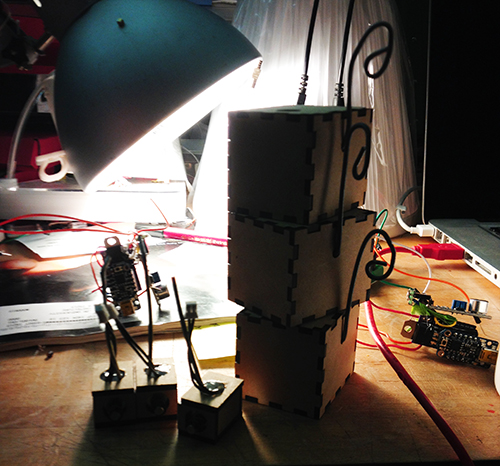
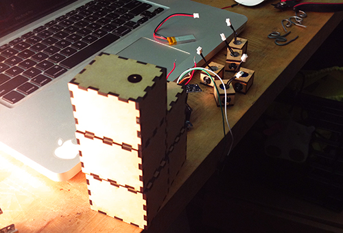
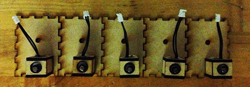
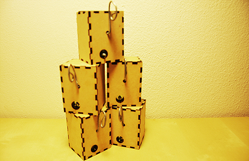
I used 3D printing enclosure to package all parts together. The holes with different sizes on the bottom are used for different usage, people can mount a hook or a suction. With these extra tools, it can be places on any surfaces. The other big hole is used for solenoid to beat the surface. The two holes on the top  side are used to show microphone and LED light separately. On each side, there is a hole for photo resistor and switch.

photo3 photo4

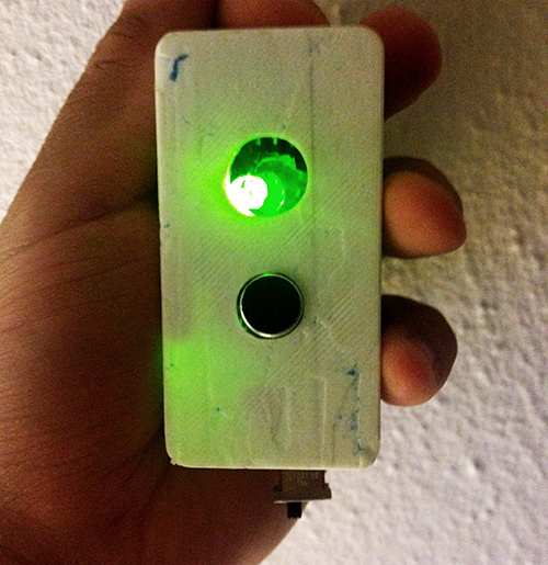
TAPO finally looks like this:

photo6 photo5 photo7 photo8 photo9

Demostration:

Final introduction video:

Conclusion & Future Work:

This project gives me a lot more than technology. I learn about how to design and develop a thing from a very raw idea, and keeping thinking about its value, target users, and possible scenarios in a quick and iterative process. I really enjoy the critique session, even though it is tough and sometimes makes me feel disappointed. The positive suggestions are always right and lead me to a high level and more correct direction. I realise my problems on motivation, design, and stroytelling from these communications. Fortunately, it gets much more reasonable from design thinking to value demonstration. I feel better when I find something more valuable and reasonable comes up in my mind. It also teaches me the significance of demonstrating my work when it is hard to describe and explain. In the public show on Dec. 6th, I found people would like to play with TAPO and try different inputs, they are curious about what kind of rhythm TAPO could generate. In the following weeks, I will refine the hardware design and rich the output (some control and digital outputs).

Acknowledge:

I would like to thank very much Ali Momeni for his advices and support on technology and idea development, and all the guest reviewers who gave me many constructive suggestions.
Final Project Presentation – Mauricio Contreras

Assignment,Final Project,Robotics,Submission,Technique — mauricio.contreras @ 11:47 pm

My fourth and final milestone and final project presentation involved real time driving of the movement of a simulated robotic arm with a haptic feedback capable gestural controller. By this time, I was interfacing with an actual ABB IRB 6640 industrial robot, and my controller was a smartphone. The IMU of the smartphone allows to read its orientation, and thus allows for mapped gestural control of the position of the head of the robot based on the tilt of the smartphone on each of its own axis. The haptic feedback is provided by the smartphone’s vibrator. Through the development up until the 3rd milestone, I had concluded that even though I had implemented already the motion control system and vibration upon the robot touching “virtual walls” (preset coordinates beyond which motion is not allowed), with the smartphone vibrating upon touching the wall, the “quality” of the motion I was getting was not enough to make it a desirable sculpting tool. I then shifted the priorities of the project in order to get better motion characteristics, as opposed to exploring further on the haptic feedback side, which up to now is only binary (touch = max vibration, not touch = 0 vibration).

Motion experiments

The motion of the ABB industrial robotic arms is limited to receive targets (6 degrees of freedom points: 3 coordinates for position and 3 for head orientation/rotation) and the motion path between them cannot be interrupted. This means updating the next target upon real time variation of the driving variable (in this case the smartphone’s orientation) is essentially not possible. I say essentially because there is a parameter of the movement instructions called “zone”, which specifies how near the head of the robot needs to be to the current target being pursued for the instruction to be considered complete, and then move to the next one. “zone = fine” means the targets have to be reached precisely. “zone = zX”, where X belongs to a group of preset numbers, allows the robot to reach “near” the target (how near is specified by the different X). Upon reaching the “zone” around the target, the next instruction in the program starts being executed.

With the above information, I considered the following alternatives for improved motion, grouped mainly in two categories:

A. Better target generation
1) Low pass filtering of the orientation
2) Keep a reception buffer with at least one more target than the current instruction (for “zone!=fine” to work well)
3) Smart generation of targets based on gesture recognition

B. Optimization of movement commands parameters
1) Setting of correct speed, step size and zone.

Out of all the available options, I started by B.1. The original motion to compare against is the fixed speed (max), fixed step size (usually 5-10 cm) and zone=fine of the first motion test, as shown in the video below:

The main progress in this direction was achieved considering variable step size in each axis based on the change of magnitude of the rotation in that axis. Also, variable speed, based on the max of the absolute values of all rotation components. Static weights were applied so that the largest step size would be around 10 cm. and the speed varies between 0-100%, with the max speed of the robot being 200 mm/s (in the manual mode of operation which is what I’ve been allowed to use). The result of these parameters may be seen below:

The resulting motion, albeit keeping its piecewise nature, seems to be much better suited to precise yet responsive control, with very little motion being performed when the rotation is near 0 (smartphones own axis aligned with the worlds coordinate system, as described here) and larger displacements being performed due to higher magnitude rotations. This resembles the way humans work on a physical piece in the sense that when precision is required movements are slow and short/local, whereas the movement between areas of precision is by definition non precise and therefore is optimized with greater speed and less accuracy. This parameter optimization was shown in the final project presentation. The final precision reached, along with smartphone vibration upon touching virtual walls (“sandbox”) was shown both in free air and also with a very simple demo. It consisted in a pencil being attached to the arm’s head and a canvas layer on top of a table, where people could draw (safely, since a “sandbox” was created which would not allow the robot to pierce through the table or adjacent wall). A video of the presentation was taken:
Assessment

The overall goal of the semester was to give a step towards an overarching ambitious project for my degree, related to being able to sculpt with a robotic arm. For this class the goal was to get acquainted with the workflow around the robotic arms present in dFab, the Dept. of Architecture digital fabrication laboratory. The factual outcome would be to use the same software that previous users are familiar with and be able to connect a gestural controller and haptic feedback capable device to drive the robots. As stated this was achieved, but the following was learnt during the project:

  • Responsiveness: real time driving of the robot seems to be crucial in order for the user to feel she/he is in actual control of the robot. The slower the response time, the harder it is to relate one’s own motion to that of the robot in an intuitive way.
  • Quality of the motion: The piecewise motion obtained due to the constraint imposed by the ways the robots are programmed (the lowest layer accessible to the user being RAPID) greatly reduces the quality with which users seem to regard the quality of the motion. “Dumb” and “robotic” were adjectives used repeatedly by users/observers. Even when good parameter choice for motion commands aided the situation, this is a key aspect to address in future development. There are other robots which are made to more closely resemble human arms and allow better real time interaction, but my degree is based on architecture and on the practical side of things I want to explore and also give dFab a creation tool useful and tuned to their setup, which means using the ABB robots. My intuition tells me that A.3, smart target generation, may provide the greatest improvement and is the next step I intend to explore in future courses.
  • Mapping: the final setup maps smartphone orientation to position of the robot’s head. Whereas it proves the concept of gestural control, it is indirect (as opposed of driving position with position which was the original intent) and the final degree of control available to the user seems far from what is desired. Presentation observers had a really tough time trying to draw on the paper provided. As it is now, the controller more resembles a 3 degree of freedom joystick, and very likely an of the shelve one that would be better in some sense could be purchased. Again my intuition tells me direct mapping (position to position and orientation to orientation) is required for “natural” control, and since my research so far points that stand alone positioning through an IMU is not solved (at least in free air) and cannot be applied to the project, seems like external sensor based technologies, such as visual motion capture (“mocap”) are necessary.
  • Why?: the question came back again from many observers in the presentation. Since the example application was drawing, many commented on the fact that humans can draw much better than the robot did. To this I replied yes, absolutely, since a naturally feeling motion has not been achieved yet, but more importantly, because the idea of using an industrial robotic arm is in tasks that would be impossible or at least very difficult for a human to do directly and cumbersome to do with a power tool, like bending/milling/etc. very hard/large materials, and that with precision and speed. Essentially, a big industrial robotic arm is made for high power/high precision/large sized applications, so anything that needs a very powerful hand tool, a position hard to reach and very high precision work in either/both scenarios a robot, with the correct instructions, can do better than bare hand. I think now that it is essential to somehow preserve the high precision nature of the robot, but still explore the liveliness of human physical sculpting. A way to do this is with a mixed analog/digital instruction set, such as in drawing software which mixes free form drawing with a mouse, but also allows for precise mathematical operations to be performed on top of that. This is tried and true for sculpting in the virtual world (any CAD software), hence it is likely that some of it can be translated in a useful way to the physical world. I intend to build this mixed human driven/software enhanced toolkit.

Code

Rapid, Android. See the Future CNC course website and ABB’s full reference for further information on RAPID.

Acknowledments

I would like to thank very much Mike Jeffers, Madeline Gannon, Zack Jacobson-Weaver, Ali Momeni, Jeremy Ficca, Joshua Bard, Garth Zegling and CMU’s Manipulation Lab for their incredible support to this project.

Final Presentation – Spencer Barton

The Black Box

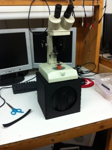
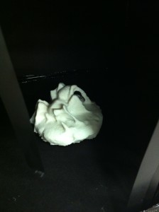
Put your hand into the black box. Inside you will find something to feel. Now take a look through the microscope. What do you feel? What do you see?

The Box and Microscope

2013-11-19 20.00.16

Inside the Box

2013-11-19 19.43.03

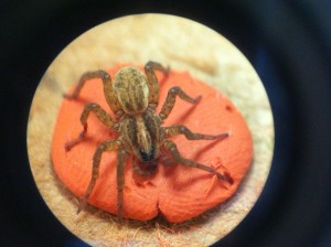
Under the Microscope

2013-11-17 00.03.12

When we interact with small objects we cannot feel them. I can hold the spider but I cannot feel it. The goal here is to enable you to feel the spider, to hold it in your hand. Our normal interaction with small things is in 2D. We see through photographs or a lens. Now I can experience the spider though touch and feel its detail. I have not created caricatures of spiders, I copied a real one. There is loss of detail but the overall form is recreated and speaks to the complexity of living organisms at a scale that is hard to appreciate.

The box enables the exploration of the spider model before the unveiling of the real spider under the microscope. The box can sense the presence of a hand and after a short delay, enabling the viewer to get a good feel of the model, a light is turned on to reveal the spider under the microscope.

Explanation of the Set-up

The Evolution of Ideas

As I created the models I found that my original goal of recreation was falling short. Instead of perfect representations of the creatures under the microscope, I had white plastic models that looked fairly abstract. The 123D models were much more realistic representations because of their color. My original presentation ideas focused around this loss of detail and the limits of the technology. However, what I came to realize was were the strengths of the technology lay: the recreation of the basic form of the object at a larger scale. For example someone could hold the spider model and get a sense of abdomen versus leg size. Rather then let someone view the model I decided to only let them feel the model.

Feedback and Moving Forward

The general feedback that I got was to explore the experience of the black box in more depth. There were two key faults with the current set-up. First the exposure of the bug under the microscope happened too soon. Time is needed for the viewer to form a questions of what is inside the black box. Only after that question is created should the answer be shown under the microscope. The experience in the box could also be augmented. The groping hand inside the box could also be exposed to other touch sensations, it could activate sound or trigger further actions. The goal would be to lead the experience toward the unveiling. For example sounds of scuttling could be triggered for the spider model.
The second piece of feedback lay with the models themselves. First it was tough to tell that the model in the box was an exact replica of the bug under the microscope. The capture process losses detail and the model creation through 3D printing adds new textures. The plastic 3D models in particular were not as interesting to touch as the experience was akin to playing with a plastic toy.

To recognize and rectify these concerns this project can be improved in a few directions. First I will improve the box with audio and a longer exposure time. Rather then look through the microscope I will have a laptop that displays the actual images that were used to make the model. The user’s view on this model with then be controlled by how they have rotated the model inside the box.
I will try another microscope and different background colors to experiment with the capture process and hopefully improve accuracy. I will redo the model slightly larger with the CNC. MDF promises to be a less distracting material to touch. Additionally the fuzziness of MDF is closer to the texture of a hairy spider.

Final Project Milestone 3 – Mauricio Contreras

Assignment,Final Project,Robotics,Submission,Technique — mauricio.contreras @ 10:26 pm

My original 3rd milestone had to do with connecting a haptic feedback controller with the simulation of robotic motion, which by this time had turned into real motion, and the device chosen as described before is a smartphone since it provides an IMU and a vibrator, all with a standard and well proven programming API.

Limitations of IMU standalone motion tracking

My original intent was to use the device’s IMU to track position and orientation, each in 3 axis, providing effectively 6 degrees of freedom. My pursuit is for a very natural gestural interaction that would mimic one’s own hand orientation and position in space, to be imitated by the robot changing it’s own head position and orientation. My assumption was that standalone positioning based on integrating the accelerometer’s readings twice was a method that must have been solved by now, and I started searching for code. Yet, to my surprise, it seems this is not true and the constraints lie mainly on the double integration, the first of which leaves a constant error, and hence the second multiplies that constant with time, meaning the error grows linear with time! The drift most algorithms (at least the ones available on the web) render is even of tens of centimeters per second, which is completely unusable for the application in mind. In the case of orientation, this is completely different because there is only one integration to be made, plus there are at any given time 2 vectors of reference against which to correct: gravity and the magnetic north. To sum up, whereas one can get very accurate orientation from an IMU, linear positioning is still very much a work in progress, the underlying reasons being physical more than technological.

This immediately cut 3 degrees of freedom from my ideal application, the most important ones at that (the assumption being that one can probably use tricks to change the head’s orientation but use real degrees of freedom for it’s position, as opposed to the other way round. This is pure intuition though). I faced the decision of changing technology to visual tracking or keep using the IMU, now only with orientation. Even though kinect based motion tacking seems to be pretty plug&play these days, I had no previous experience and decided the semester was too advanced to have a setback as not being able to show anything functional in the end, whereas I was already somewhat acquainted at this time with the smartphone workflow I had developed. I decided then to stay on this path.

Orientation based linear motion control, first tests

I devised a TCP/IP socket based client (Android smartphone) – server (robot controller) application. It uses the smartphones orientation (software sensor provided by Android based on fusing the raw information from accelerometer, gyroscopes and magnetometer/compass) in each axis to generate steps that offset the robots head position in each axis.

The motion result was pretty much just as cut as what I had obtained with hardcoded targets, which left me with a feeling of disappointment. See video below, and please notice how unnatural this piecewise movement feels.

This piecewise motion is not related to the smartphone input information, but to the way the robot is controlled. Through the trials, becoming acquainted with people who have done extensive work with the robots (Mike Jeffers, Madeline Gannon, Zack Jacobson-Weaver, Ali Momeni, Jaremy Ficca, Josh Bard, Kevyn McPhail, up to then) and online research, I came to know that at least ABB robots, being developed for industrial use, are aimed towards rigid precision. This means motion commands are based on targets and are not meant to be interrupted in the middle, which is exactly what is required for responsive gestural control (real time interrupts). The next and final milestone shows the way of how I’ve dealt with this limitation.

Final Project Milestone 3 – Ding Xu

Audio,Final Project,Machine Vision,OpenCV — Ding Xu @ 10:24 pm

1. GPIO control board soldering

In order to use GPIO of RPI for digital signal control, I built a control protoboard  with two switches and two push buttons connecting a pull-up/pull-down registers respectively. A female header was used to connect the GPIO of RPI to get the digital signal.

In RPI, I used the library WiringPi for GPIO signal reading. After compiling this library and include the header files, three easy steps are used to read the data from digital pins: (1). wiringPiSetup() (2). set up pinmode: PinMode(GPIOX,INPUT) and (3). digitalRead(GPIOX) or digitalWrite(GPIOX)

photo_7(1)


2. software design

In openframeworks, I used  the library Sndfile for recording and ofSoundPlayer for sound output. There are two modes: capture and play. Users are expected to record as many as sounds in their lives and take an image each time recording a sound. Then in the play mode, the camera will capture a surrounding image and the sound tracks of similar images will be played.  The software workflow is as follows:

Capture:

Play:

code

3. system combination

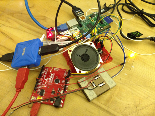
Connecting the sound input/output device, RPI, singal control board and camera, the system is as follows:

photo_31

photo30

Final Project Documentation: The Wobble Box

Assignment,Audio,Final Project,Laser Cutter,Max,Sensors — Tags: , , , — Jake Berntsen @ 5:16 pm

After taking time to consider exactly what I hope to accomplish with my device, the aim of of my project has somewhat shifted. Rather than attempt to build a sound-controller of some kind that includes everything I like about current models while implementing a few improvements, I’ve decided to focus only on the improvements I’d like to see. Specifically, the improvements I’ve been striving for are simplicity and interesting sensors, so I’ve been spending all of my time trying to make small devices with very specific intentions. My first success has been the creation of what I’m calling the “Wobble Box.”
IMG_1522

IMG_1524

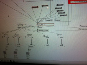
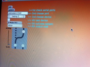
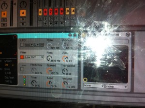
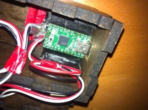
Simply stated, the box contains two distance sensors which are each plugged into a Teensy 2.0.  I receive data from the sensors within Max, where I scale it and “normalize” it to remove peaks, making it more friendly to sound modulation.  While running Max, I can open Ableton Live and map certain audio effects to parameters in Max.  Using this technique I assigned the distance from the box to the cutoff of a low-pass filter, as well as a slight frequency modulation and resonance shift.  These are the core elements of the traditional Jamaican/Dubstep sound of a “wobble bass,” hence the name of the box.  While I chose this particular sound, the data from the sensors can be used to control any parameters within Ableton.

IMG_1536

IMG_1535

IMG_1532

Designing this box was a challenge for me because of my limited experience with hardware; soldering the distance sensors to the board was difficult to say the least, and operating a laser-cutter was a first for me.  However, it forced me to learn a lot about the basics of electronics and I now feel confident in my ability to design a better prototype that is smaller, sleeker, and more compatible with similar devices.  I’ve already begun working on a similar box with joysticks, and a third with light sensors.  I plan to make the boxes connectible with magnets.
IMG_1528For my presentation in class, I will be using my device as well as a standard Akai APC40.  The wobble box is not capable or meant to produce its own melodies, but rather change effects on existing melodies.  Because of this, I will be using a live-clip launching method to perform with it, making a secondary piece of hardware necessary.


Final Project Milestone #3: Liang

Final Project,Laser Cutter,Rhino3D,Sensors — lianghe @ 2:23 am

1. My boards arrived!!

After about 12 days, OSH Park fabricated and delivered my boards. Yes, they are fantastic purple and look like exactly what I expect. I soldered and assembled every components together to test the board. Finally, all boards work with all the components but the transistor. I used smaller one instead of TIP 120. For some reason, it could work with Trinket board. So, I used TIP 120 again with my final board.

photo


2. Add Microphone Module!

To solve the problem of gestures and how user interacts with cup and Tapo, I decided to use a microphone to record user’s input (oral rhythm, voice, and even speech). The idea is quite simple: since the electret microphone turns analog voice data into digital signal, I can just make use of the received signal and generate certain beat for a rhythm. That is more reasonable interaction for users and my gestures can be put into two categories: trigger the recording and clear the recorded rhythm. The image below shows the final look of the hardware part, including the PCB board, Trinket board, transistor, step-up voltage regulator, solenoid, accelerometer, electret microphone, and a switch.

photo

photo1


photo2


3. Fabrication!

All parts should be enclosed in a little case. At the beginning I was thinking of 3D printing a case and using magnets to fix the case on the cup. I 3D printed some buckets with magnet to see the magnetic power. It seemed not very well in attracting the whole case. The other thing looks difficult for 3D printing case was that it was not easy to put the entire hardware part in and get it out.

photo copy

Then I focused on laser cutting.  I created a box for each unit and drilled one hole for solenoid, one hole for microphone and a hole for hook. I experienced three versions: the first one left one hole for the wire of solenoid to go through, thereby connecting with the main board. But the solenoid could not be fixed quite well (I used strong steel wire to support it); The second version put the solenoid inside the box and opened a hole on the back facet, so that it could tap the cup it was mounted on, but the thickness of the box avoided the solenoid to touch object outside; In the final version I drilled a hole on the upper plate for the switch, and modified the construction for solenoid.

photo

photo copy


Version 1

photo copy

Version 2

photo copy

Solenoids

DSC_0110 copy1

Version 3

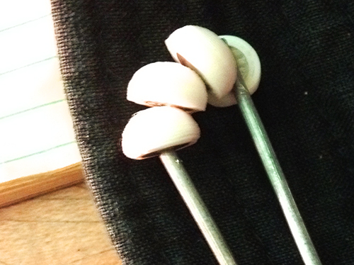
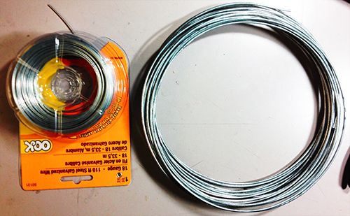
Another thing is the hook. I started with a thick and strong steel wire and resulted in that it could not be bended easily. Then I used a thinner and softer one, so that it could be bended to any shape as the user wished.

photo copy

4. Mesh up codes and test!!

Before program the final unit, I programmed and tested every part individually. The accelerometer and the gestures worked very well, the solenoid worked correctly, and I could record user’s voice by microphone and transferred it to certain pattern of beats. Then the challenge is how to make a right logic for all the things work together.  After several days’ programming, testing, debugging, I meshed up all logics together. The first problem I met was the configuration of Trinket, which led to my code could not be burned to the board. Then the sequence of different module messed up. Since the micro controller processed data and events in a serial sequence, so the gesture data could not be “timely” obtained while the beats of solenoid depended on several delays.

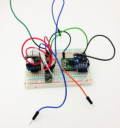
I built a similar circuit, in which my custom PCB was replaced by a breadboard, to test my code. In the test, I hoped to check if my parameters for the interval of every piece of rhythm was proper, if the data number of the gesture set was enough to recognise gestures, if specific operation causes specific events, and most importantly, if the result looked good and reasonable.

Here is the test unit:

photo copy

Here is a short video demo of the test:

Final Project Milestone 2 – Ding Xu

Audio,Final Project,Laser Cutter,OpenCV — Ding Xu @ 11:05 pm

In my second milestone. I finished the following stuff:

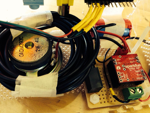
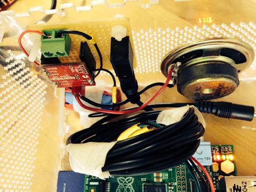
1. sound output amplification circuit. I first used a breadboard to test the audio output circuit using an amplifier connecting a speaker with a switch to augment the output sound and then  finished soldering a protoboard.

photo_2

photo_7 (2)

photo_8 (2)

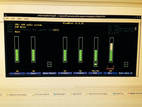
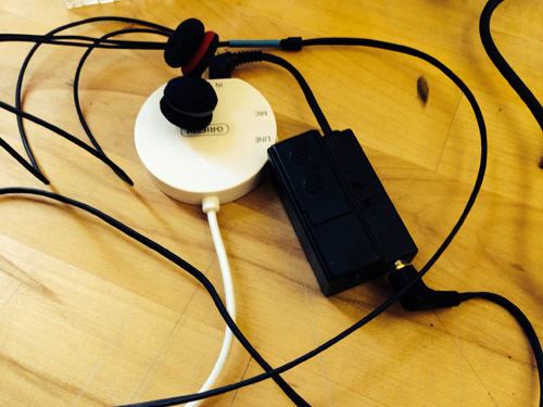
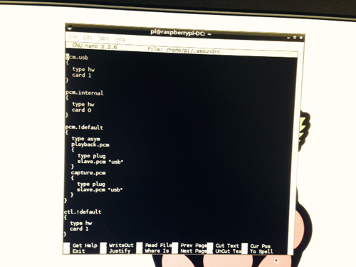
2. Sound capture device: a mic with a pre-amp connecting an usb audio card was used for sound input. However, it spent me a lot of  time to configure the parameters in the Raspberrry Pi to make it work. I referred to several blog posts in the website to get asoundrc and asound.conf file well set for audio card select and alsa mixer for control. A arecord and aplay command were used to test the recording in linux. Then I revised an addon of OF ofxLibsndFileRecorder to achieve recording. However, from the testing result, the system is not very robust, sometimes the audio input will fail and sometimes the play speed will much faster than recording speed, accompanying much noise.

photo_11照片2

alsamixer

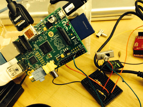
3. GPIO test: in order to test control the audio input and output with  switch and button. I first used a breadboard connecting a switch with a pull-up or pull down resister as the recording/play control.

photo_22

4. Case building: a transparent case using laser cut was built.

photo(1)

5. Simulink test: I searched that simulink recently supported the raspberry Pi with several well developed modules. So I tried to install an image of Simulink and run some simple demos with that platform. I also tested the GPIO control for triggering the switch between two sine wave generator in Simulink.

gpio1

Final Project Milestone 2 – Mauricio Contreras

Assignment,Final Project,Robotics,Submission,Technique — mauricio.contreras @ 10:02 pm

Log

My second milestone was about simulating the motion of a robotic arm within the software workflow that had been explored in the first milestone (Rhino + Grasshopper + HAL). Upon getting acquainted with the capabilities of these pieces of softwares and understanding more about the possible constraints and needs of the instrument, I realized that REAL TIME driving of the robotic arm was a major requirement. Just imagine sculpting with your arm moving with a few seconds lag after your movement intention and you’ll see why. The software workflow described above is great for offline materialization of 3D designs, but not necessarily for real time control. Even though feasible, people from the lab commented about possible lag issues, which made me want to try out the real motion of the robot, even with simple commands, as soon as possible. I found procuring the tools to run in my own machine rather difficult: All of them are Windows only, so at first I got a virtual machine from Ali Momeni with everything preloaded, but it ran excruciatingly slow (even when I changed my computer to the latest Macbook Pro). Then I tried creating my own virtual machine from scratch, and installed Rhino and Grasshopper with success. Yet HAL’s developer webpage was down and I had problems procuring tutorial training for it. When I asked for help with this, people recommended to learn the former 2 tools first and then use HAL. This seemed reasonable but I was under time constraints (by choice) to test the robots motion as soon as possible with a configuration that would generate the least lag, and evaluate if that optimal setup would prove to be responsive enough to match the target application of the instrument, which is sculpting.

Early motion tests

I then turned to writing my own RAPID code, and quickly was able to generate a routine to move the head of the robot in a square in the air, as shown in the following video.

The routine was based on offsetting the current location by steps in each axis, but also waiting for a digital input state before each small step. Since the robot accepts 24 V digital inputs, I would have had to use a power source or do a conversion circuit from the standard micro controllers 5/3.3 V outputs. That is not difficult but I assumed that the DI of the robots had pull down resistors and just made it wait for DI=0 before each motion. Since the shape was completed that thesis was proven. Also, the motion seemed “cut”, as if doing start-pause-restart in every step, as opposed to a seamlessly continual motion that would have occurred either if the lag on processing the digital input was very low or depending on motion configuration of the robot (i.e. there may be other motion commands that would output less of a “cut” motion). I removed the wait for DI statements with no appreciable effect, hence the motion commands were the issue. To see the effect of this when driving the robot with gestures, and based on previous code for motion (FUTURE CNC LINK), I started writing a TCP/IP socket based client (Android smartphone) – server (robot controller) application, which will be outlined in the next milestone posting.

Assessment

Up to this milestone, just getting access to the robots themselves and being able to move them in a hardcoded fashion I consider a success by itself, yet it is clear that new, unforeseen difficulties have appeared.

Final Project Presentation: Liang

Final Project,Laser Cutter,Sensors — lianghe @ 2:52 am

The final project goes wrong with Pin conflict on Trinket. Since I use Pin #1 to read microphone’s digital data and Pin #2 (Trinket requires “1”, which means A1, instead of “2” in code) to read analog X-axis accelerometer data,  it gets confused when I have to write the same command “PinMode(1, INPUT);” in the code to execute both data read. It leads to the failure of reading microphone and accelerometer at the same time. Annoyingly, I had to use Teensy at the very last minute instead to perform my demo. It was not robust and that good, and very preliminary. I felt sorry for the audience and reviewers that night. However, they gave me a lot of feedback and suggestions on potential revise and development. Here I sum up some key points:

1. My biggest problem is that I attempt to cover many scenarios and applications, which is so generic that confuses audiences and eventually lose its value. It fails to address the major problem it tries to figure out, or the goal for its exist. It throws abstract pictures to audience, leave alone under the situation that it cannot work.

2. The gesture seems weird since the microphone works part the role of the gesture. I would argue that the gesture is kind of the way people feel the liquid in the cup. Honestly, when I design the gesture, I find only one gesture (shake) is meaningful for people.

3. Other formations. No matter what kind of stuff I want to create and make, it should respect my motivation and its goal. So, again it goes back to “Point #1”.

I agree with most of the comments in the critique and they drive me recall my original motivation: I know cup has resonance with liquid, cup has material, people use cup, and it can be an instrument to perform music. In the past weeks, I continue to do some research how to make use of these characters and what kind of music it can generate. Here I have some answers: it can generate beats, then rhythm, so it can perform some kind of percussion performance. Besides cups, other objects also have resonance property. When I look back at these, I narrow down my scenario for Tapo and come up with a new but iterative design and development solution.

Redefine the story for TAPO

Physical objects have resonance property and specific material. Tap object gives different sound feedback and percussion experience. People are used to making rhythms by beating objects. So, why not provide a tangible way not only allowing people to make rhythms with physical objects around she/he, but also enriching the experience by some computational methods. The ultimate goal for this project is that ordinary people can make and play rhythms with everyday objects, even perform a piece of percussion performance.

Next Page »
This work is licensed under a Creative Commons Attribution-Noncommercial-Share Alike 3.0 Unported License.
(c) 2024 Hybrid Instrument Building 2014 | powered by WordPress with Barecity