Final Project Documentation: The Wobble Box 2.0

Arduino,Assignment,Audio,Final Project,Instrument,Max,Sensors,Software — Tags: — Jake Berntsen @ 9:46 pm

Presenting my original “wobble box” to the class and Ali’s guests was a valuable experience.  The criticisms I received were relatively consistent, and I have summarized them to the best of my ability below:

  • The box cannot be used to create music as an independent object.  When I performed for the class at the critique, I was using an Akai APC40 alongside the wobble box.  I was using the APC to launch musical ideas that would then be altered using the wobble box, which I had synced to a variety of audio effects.  The complaint here was that it was unclear exactly how much I was doing to create what the audience was hearing in real time, and very clear that I wasn’t controlling 100% of the noises coming out of my computer.  At any rate, it was impossible to trigger midi notes using the wobble box, which meant the melody had to come from an external source.
  • The box only has one axis to play with.  At the time of the critique, the wobble box only had one working distance sensor attached to the Teensy, which meant I could only control one parameter at a time with my hand.  Many spectators commented that it seemed logical to have at least two, allowing me to get more sounds out of various hand motions, or even using two hands at once.
  • The box doesn’t look any particular way, and isn’t built particularly well.  The wobble box was much bigger than it needed to be to fit the parts inside it, and little to no thought went into the design and placement of the sensors.  It was sometimes difficult to know exactly when it was working or not, and some of the connections weren’t very stable.  Furthermore, the mini-USB plug on the side of the device sometimes moved around when you tried to plug in the cord.

In the interested of addressing the concerns above, I completely redesigned the wobble box, abandoning the old prototype for a new model.
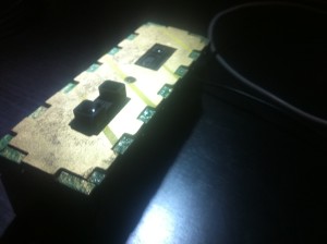
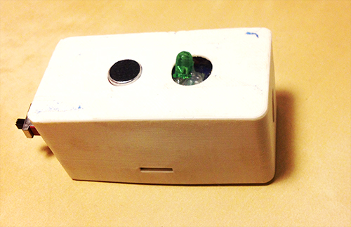
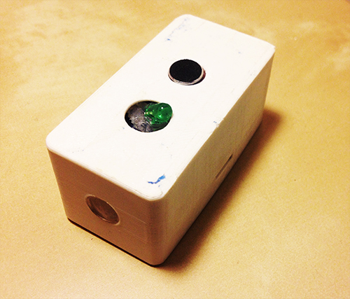
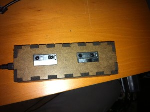
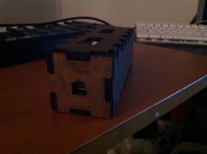
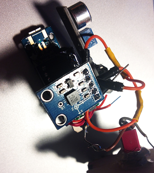
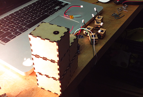
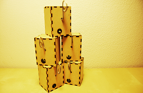
IMG_1636 The most obviously improved element of the new box is the design.  Now that I knew exactly what the necessary electronic parts were, I removed all the extra space in the box.  The new design conserves about three square inches of space, and the holes cut for the distance sensors are much neater.

IMG_1643

I applied three layers of surface treatment; a green primer, a metallic overcoat, and a clear glaze.  The result is a luminescent coloring, and a rubber-esque texture that prevents the box from sliding around when placed on a wooden surface.  In my opinion, it looks nice.

IMG_1639IMG_1645

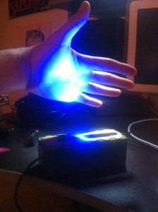
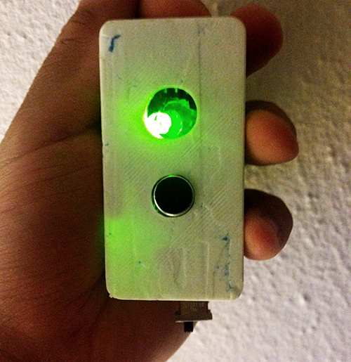
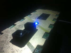
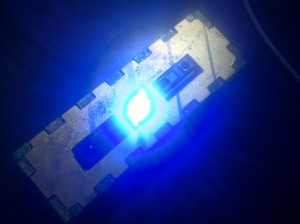
A strong LED light was placed exactly in between the two distance sensors, illuminating the ideal place for the user to put his/her hand.  This also provides a clue for the audience, making it more clear exactly what the functionality of the box is by illuminating the hand of the user.  The effect can be rather eery in dark rooms.  Perhaps most importantly, it indicates that the Teensy micro-controller has been recognized by Max, a feature lacking in the last prototype.  This saved me many headaches the second time around.
IMG_1640

IMG_1644

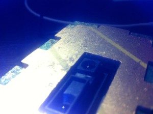
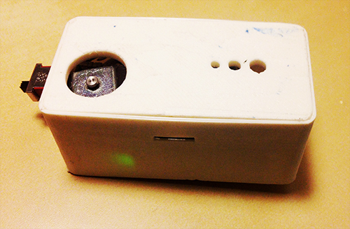
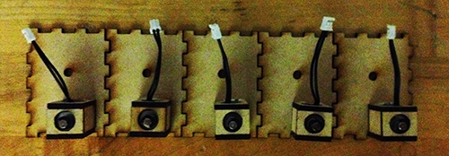
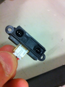
The new box has two new distance sensors, with differing ranges.  One transmits very fine values between about 2 inches and 10 inches, the other larger values between about 4 and 18 inches.  Staggering the ranges like this allows for a whole new world of control for the user, such as tilting the hand from front to back, using two hands with complete independence, etc.
IMG_1642

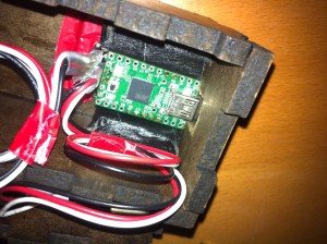
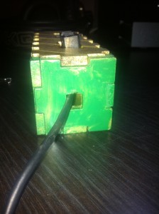
Finally, I moved the entire USB connection to the interior of the device, electing to instead just create a hole for the cord to come out.  After then securing the Teensy within the box, the connection was much stronger than it was in the previous prototype.

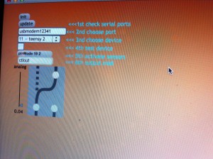
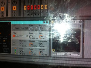
In addition to fixing the hardware, I created a few new software environments between Max and Ableton that allow for more expressive use of the box.  The first environment utilized both Max and Ableton Live to create an interactive art piece.  As the user stimulated the two distance sensors, a video captured by the laptop camera would be distorted along with an audio track of the user talking into the computer microphone.  Moving forward, my goals were to extend the ability to use the box as a true instrument, by granting a way to trigger pitches using only the box and a computer.  To achieve this, I wrote a max for live patch that corresponds a note sequence-stepper with a microphone.  Every time the volume of the signal picked up by the microphone exceeds a certain threshold, the melody goes forward by one step.  Using this, the user can simply snap or clap to progress the melody, while using the box to control the timbre of the sound.  I then randomized the melody so that it selected random notes from specific scales, as to allow for improvisation.  The final software environment I wrote, shown below, allows for the user to trigger notes using a midi keyboard, and affect the sounds in a variety of ways using the box.  For the sake of exhibiting how this method can be combined with any hardware the user desires, I create a few sounds on an APC40 that I then manipulate with the box.

Final Project “TAPO”: Liang

TAPO: Speak Rhythms Everywhere

Idea Evolution:

This project comes from the original idea that people can make rhythms through the resonant property and material of cups and interacting with cups. However, as the project progresses, it is more interesting and proper for people to input the rhythms by speaking than do gestures on cups. It also extends the context from cups to any surface because of the fact that each object has resonant property and specific material. So, the final design and function of TAPO have a significant change from the very raw idea. The new story here is:

“Physical objects have resonance property and specific material. Tap object gives different sound feedback and percussion experience. People are used to making rhythms by beating objects. So, why not provide a tangible way not only allowing people to make rhythms with physical objects around she/he, but also enriching the experience by some computational methods. The ultimate goal for this project is that ordinary people can make and play rhythms with everyday objects, even perform a piece of percussion performance.”

Design & Key Features:

TAPO is an autonomous device that generates rhythms according to people’s input (speech, tapping, making noise). TAPO can be placed on different surfaces, like desk, paper, ground, wall, window… With different material and the object’s resonant property, it is able to create different quality of sound. People’s input gives the pattern of rhythm.

System diagram

a) voice, noise, oral rhythm, beat, kick, knock, oral expression… can be the user input

b) using photo resistor to trigger recording

c) get rid of accelerometer, add led to indicate the state of recording and rhythm play

Hardware

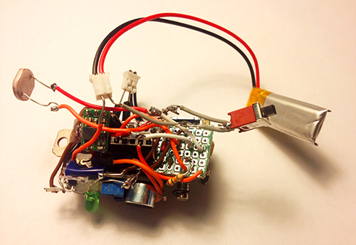
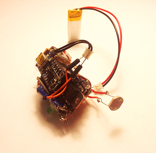
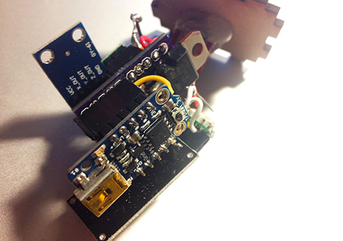
It is composed of several hardware components: a solenoid, a microphone electret, a transistor, a step-up voltage regulator, a Trinket board, a colourful LED, a photocell, a switch and a battery.

photo1


photo2


Fabrication

I used 3D printing enclosure to package all parts together. The holes with different sizes on the bottom are used for different usage, people can mount a hook or a suction. With these extra tools, it can be places on any surfaces. The other big hole is used for solenoid to beat the surface. The two holes on the top  side are used to show microphone and LED light separately. On each side, there is a hole for photo resistor and switch.

photo3 photo4

TAPO finally looks like this:

photo6 photo5 photo7 photo8 photo9

Demostration:

Final introduction video:

Conclusion & Future Work:

This project gives me a lot more than technology. I learn about how to design and develop a thing from a very raw idea, and keeping thinking about its value, target users, and possible scenarios in a quick and iterative process. I really enjoy the critique session, even though it is tough and sometimes makes me feel disappointed. The positive suggestions are always right and lead me to a high level and more correct direction. I realise my problems on motivation, design, and stroytelling from these communications. Fortunately, it gets much more reasonable from design thinking to value demonstration. I feel better when I find something more valuable and reasonable comes up in my mind. It also teaches me the significance of demonstrating my work when it is hard to describe and explain. In the public show on Dec. 6th, I found people would like to play with TAPO and try different inputs, they are curious about what kind of rhythm TAPO could generate. In the following weeks, I will refine the hardware design and rich the output (some control and digital outputs).

Acknowledge:

I would like to thank very much Ali Momeni for his advices and support on technology and idea development, and all the guest reviewers who gave me many constructive suggestions.

Final Project Presentation – Ziyun Peng

Assignment,Final Project,Max,Sensors — ziyunpeng @ 10:20 pm

Face Yoga Game

Idea

There’s something interesting about the unattractiveness that one goes through on the path of pursuing beauty. You put on the facial mask to moisturize and tone up your skin while it makes you look like a ghost. You do face yoga exercises in order to get rid of some certain lines on your face but at the mean time you’ll have to many awkward faces which you definitely wouldn’t want others to see. The Face Yoga Game aims at amplifying the funniness and the paradox of beauty by making a game using one’s face.

Set-up

Myoelectric sensors -> Arduino —Maxuino—> Max/MSP (gesture recognition)—OSC—> Processing (game)

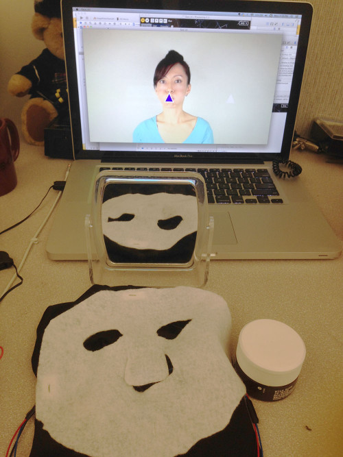
Myoelectric sensor electrodes are replaced with electric fabrics so to be sewed onto a mask that the player is going wear. The face gestures that correspond to the face yoga video are pre-learnt in Max/MSP using the Gesture Follower external developed in IRCAM. When the player is making facial expressions under the mask, it will be detected in Max/MSP, the corresponding gesture number will be sent to Processing to determine if the player is performing the right gesture.

How does the game work?

Face_Yoga


The game is in the scenario of “daily beauty care” where you have a mirror, a moisturizer and a screen for game play.

Step 1: Look at the mirror and put on the mask

Step 2: Apply the moisturizer (for conductivity)

Step 3: Start practicing with the game!

The mechanism is simple, the player is supposed to do the same gesture as the instructor does in order to move the object displayed on the screen to the target place.

The final presentation is in a semi-performative  form to tell

Final Project Documentation: The Wobble Box

Assignment,Audio,Final Project,Laser Cutter,Max,Sensors — Tags: , , , — Jake Berntsen @ 5:16 pm

After taking time to consider exactly what I hope to accomplish with my device, the aim of of my project has somewhat shifted. Rather than attempt to build a sound-controller of some kind that includes everything I like about current models while implementing a few improvements, I’ve decided to focus only on the improvements I’d like to see. Specifically, the improvements I’ve been striving for are simplicity and interesting sensors, so I’ve been spending all of my time trying to make small devices with very specific intentions. My first success has been the creation of what I’m calling the “Wobble Box.”

IMG_1522

IMG_1524

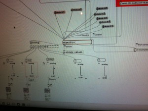
Simply stated, the box contains two distance sensors which are each plugged into a Teensy 2.0.  I receive data from the sensors within Max, where I scale it and “normalize” it to remove peaks, making it more friendly to sound modulation.  While running Max, I can open Ableton Live and map certain audio effects to parameters in Max.  Using this technique I assigned the distance from the box to the cutoff of a low-pass filter, as well as a slight frequency modulation and resonance shift.  These are the core elements of the traditional Jamaican/Dubstep sound of a “wobble bass,” hence the name of the box.  While I chose this particular sound, the data from the sensors can be used to control any parameters within Ableton.
IMG_1536

IMG_1535

IMG_1532

Designing this box was a challenge for me because of my limited experience with hardware; soldering the distance sensors to the board was difficult to say the least, and operating a laser-cutter was a first for me.  However, it forced me to learn a lot about the basics of electronics and I now feel confident in my ability to design a better prototype that is smaller, sleeker, and more compatible with similar devices.  I’ve already begun working on a similar box with joysticks, and a third with light sensors.  I plan to make the boxes connectible with magnets.

IMG_1528For my presentation in class, I will be using my device as well as a standard Akai APC40.  The wobble box is not capable or meant to produce its own melodies, but rather change effects on existing melodies.  Because of this, I will be using a live-clip launching method to perform with it, making a secondary piece of hardware necessary.


Final Project Milestone #3: Liang

Final Project,Laser Cutter,Rhino3D,Sensors — lianghe @ 2:23 am

1. My boards arrived!!

After about 12 days, OSH Park fabricated and delivered my boards. Yes, they are fantastic purple and look like exactly what I expect. I soldered and assembled every components together to test the board. Finally, all boards work with all the components but the transistor. I used smaller one instead of TIP 120. For some reason, it could work with Trinket board. So, I used TIP 120 again with my final board.

photo


2. Add Microphone Module!

To solve the problem of gestures and how user interacts with cup and Tapo, I decided to use a microphone to record user’s input (oral rhythm, voice, and even speech). The idea is quite simple: since the electret microphone turns analog voice data into digital signal, I can just make use of the received signal and generate certain beat for a rhythm. That is more reasonable interaction for users and my gestures can be put into two categories: trigger the recording and clear the recorded rhythm. The image below shows the final look of the hardware part, including the PCB board, Trinket board, transistor, step-up voltage regulator, solenoid, accelerometer, electret microphone, and a switch.

photo

photo1


photo2


3. Fabrication!

All parts should be enclosed in a little case. At the beginning I was thinking of 3D printing a case and using magnets to fix the case on the cup. I 3D printed some buckets with magnet to see the magnetic power. It seemed not very well in attracting the whole case. The other thing looks difficult for 3D printing case was that it was not easy to put the entire hardware part in and get it out.

photo copy

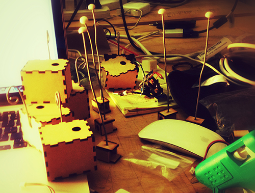
Then I focused on laser cutting.  I created a box for each unit and drilled one hole for solenoid, one hole for microphone and a hole for hook. I experienced three versions: the first one left one hole for the wire of solenoid to go through, thereby connecting with the main board. But the solenoid could not be fixed quite well (I used strong steel wire to support it); The second version put the solenoid inside the box and opened a hole on the back facet, so that it could tap the cup it was mounted on, but the thickness of the box avoided the solenoid to touch object outside; In the final version I drilled a hole on the upper plate for the switch, and modified the construction for solenoid.

photo

photo copy


Version 1

photo copy

Version 2

photo copy

Solenoids

DSC_0110 copy1

Version 3

Another thing is the hook. I started with a thick and strong steel wire and resulted in that it could not be bended easily. Then I used a thinner and softer one, so that it could be bended to any shape as the user wished.

photo copy

4. Mesh up codes and test!!

Before program the final unit, I programmed and tested every part individually. The accelerometer and the gestures worked very well, the solenoid worked correctly, and I could record user’s voice by microphone and transferred it to certain pattern of beats. Then the challenge is how to make a right logic for all the things work together.  After several days’ programming, testing, debugging, I meshed up all logics together. The first problem I met was the configuration of Trinket, which led to my code could not be burned to the board. Then the sequence of different module messed up. Since the micro controller processed data and events in a serial sequence, so the gesture data could not be “timely” obtained while the beats of solenoid depended on several delays.

I built a similar circuit, in which my custom PCB was replaced by a breadboard, to test my code. In the test, I hoped to check if my parameters for the interval of every piece of rhythm was proper, if the data number of the gesture set was enough to recognise gestures, if specific operation causes specific events, and most importantly, if the result looked good and reasonable.

Here is the test unit:

photo copy

Here is a short video demo of the test:

Final Project Presentation: Liang

Final Project,Laser Cutter,Sensors — lianghe @ 2:52 am

The final project goes wrong with Pin conflict on Trinket. Since I use Pin #1 to read microphone’s digital data and Pin #2 (Trinket requires “1”, which means A1, instead of “2” in code) to read analog X-axis accelerometer data,  it gets confused when I have to write the same command “PinMode(1, INPUT);” in the code to execute both data read. It leads to the failure of reading microphone and accelerometer at the same time. Annoyingly, I had to use Teensy at the very last minute instead to perform my demo. It was not robust and that good, and very preliminary. I felt sorry for the audience and reviewers that night. However, they gave me a lot of feedback and suggestions on potential revise and development. Here I sum up some key points:

1. My biggest problem is that I attempt to cover many scenarios and applications, which is so generic that confuses audiences and eventually lose its value. It fails to address the major problem it tries to figure out, or the goal for its exist. It throws abstract pictures to audience, leave alone under the situation that it cannot work.

2. The gesture seems weird since the microphone works part the role of the gesture. I would argue that the gesture is kind of the way people feel the liquid in the cup. Honestly, when I design the gesture, I find only one gesture (shake) is meaningful for people.

3. Other formations. No matter what kind of stuff I want to create and make, it should respect my motivation and its goal. So, again it goes back to “Point #1”.

I agree with most of the comments in the critique and they drive me recall my original motivation: I know cup has resonance with liquid, cup has material, people use cup, and it can be an instrument to perform music. In the past weeks, I continue to do some research how to make use of these characters and what kind of music it can generate. Here I have some answers: it can generate beats, then rhythm, so it can perform some kind of percussion performance. Besides cups, other objects also have resonance property. When I look back at these, I narrow down my scenario for Tapo and come up with a new but iterative design and development solution.

Redefine the story for TAPO

Physical objects have resonance property and specific material. Tap object gives different sound feedback and percussion experience. People are used to making rhythms by beating objects. So, why not provide a tangible way not only allowing people to make rhythms with physical objects around she/he, but also enriching the experience by some computational methods. The ultimate goal for this project is that ordinary people can make and play rhythms with everyday objects, even perform a piece of percussion performance.

Final Project Milestone One: Jake Berntsen

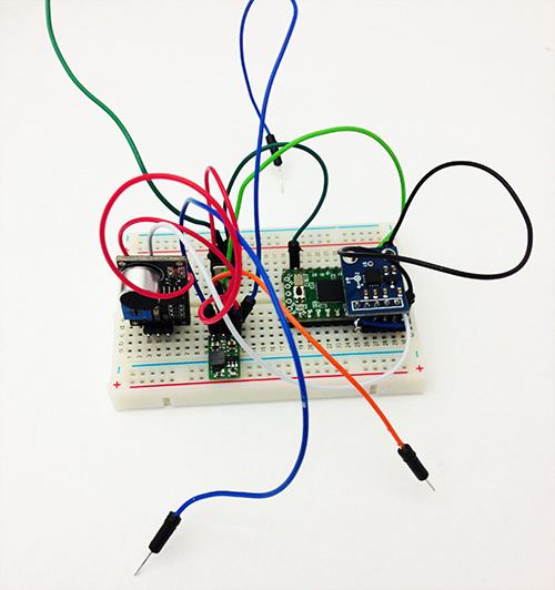
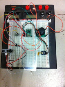
My struggles thus far in this class have rested almost entirely on the physical side of things; I’m relatively keen with regards to using relevant software, but my ability to actually build devices is much less developed, to say the least.  With this in mind, I decided to make my early milestones for my final project focus entirely on the most technically challenging aspects in terms of electrical engineering; specific to my project, this meant getting all of the analog sensors running into my Teensy to obtain data I could manipulate in Max.  To do so meant a lot of prototyping on a breadboard.
IMG_1449

After exploring a wide variety of sensors, I found a few that seemed to give me a sharp control of the data received by Max.  One of my goals for this project is to create a controller that offers a more nuanced musical command than the current status quo, and I believe that the secret to this lies within more sensitive sensors.


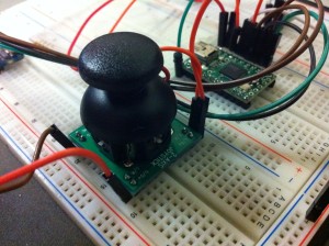
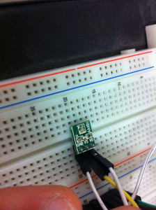
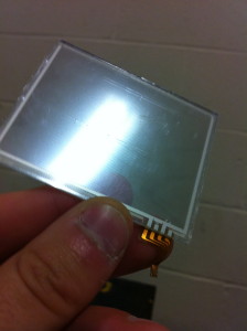
The sensors I chose are picture below: Joysticks, Distance Sensors, Light Sensors, and a Trackpad.

Joystick


Light Sensor


IMG_1445


IMG_1447


All of the shown sensors have proven to work dependably, with the exception of some confusion regarding the input sensors of the trackpad.  The trackpad I am using is from the Nintendo DS gaming device, and while it’s relatively simple to get data into Arduino, I’m having trouble getting data all the way into Max.

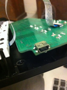
The other hardware challenge that I was facing this week was fixing the MPK Mini device that I planned to incorporate into my controller.  The problem with it was a completely detached mini USB port that is essential to the usage of the controller.  Connecting a new port to the board is a relatively simple soldering job, and I successfully completed this task despite my lack of experience with solder.  However, connecting the five pins that are essential for getting data from the USB is a much more complicated task, and after failing multiple times, I decided to train myself a bit in soldering before continuing.  I’ve not yet seen success, but I’ve improved greatly in the past few days alone and feel confident that I will have the device working within the week.

IMG_1451

IMG_1450


If I continue working at this rate, I do believe that I will finish my project as scheduled.  While I was anticipating only being able to use the sensors that I could figure out how to use, I instead was able to make most of the ones I tried work with ease and truly choose the best one.

IMG_1452

Final Project Milestone 1 – Ding Xu

We live in a world surrounding by different environments. Since music could have mutual influence with human’s emotions, environments also embrace some parameters which could get involved in that process. In certain content, environment may be a good indicator to generate certain “mood” to transfer into music and affect people’s emotions. Basically, the purpose of this project is to build a portable music player box which could sense the surrounding environment and generate some specific songs to users.

This device has two modes: the search mode and generate mode. In the first mode, input data will be transformed into some specific tags according to its type and value; then these tags are used to described a series of existing songs to users. In the second mode, two cameras are used to capture ambien images to create a piece of generative music. I will finish the second mode in this class.

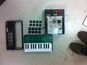
In mode 2, for each piece of song, two types of images will be used. The first one is a music image captured by an adjustable camera and the content of this image will be divided into several blocks according to their edge pixels and generate several notes according to their color. The second image is a texture one captured by a camera with a pocket microscope. When the device is placed on the different materials, corresponding texture will be distinguished and attach different instrument filter to music.

Below is a list of things I finished in the first week:

  • System design
  • platform test and select specific hardware and software for project
  • Be familiar with raspberry pi OS and Openframeworks
  • Experiment about data transmission among gadgets
  • Serial communication between arduino/teensy and Openframeworks
  • get a video from camera and play sound in openframeworks

Platform test:

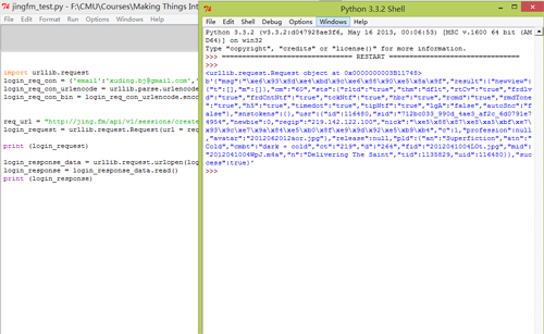
Since this device is a portable box which need to be played without supporting of a PC,  therefore, I want to use raspberry pi, arduino and sensors (including camera and data sensors) to do this project. As for the software platform, I chose openframeworks as the maor IDE and plan to use PD to generate sound notes, connecting it with openframeworks for control. Moreover, it’s more comfortable for me to use C++ rather than python, since I spent much more time to achieve some a HTTP request to log into Jing.FM in python.

Python test

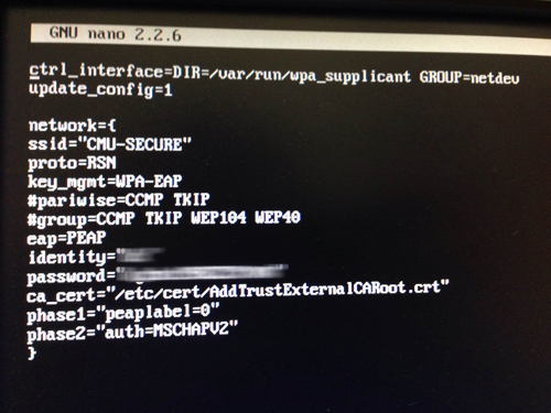
Raspberry Pi Network setting

As a fresh hand for Raspberry Pi without any knowledge about Linux, I got some problems when accessing into the CMU-secure wifi with Pi since the majority of tutorial is about how to connect the Pi with a router, and CMU-secure is not the case. Finally, I figured it out with the help of a website explaining the very specific parameters in wpa_supplicant.conf, the information provided by CMU computing service website and copying the certificate file into Pi. I also want to mention that each hardware which use CMU wifi need to register the machine in netreg.net.cmu.edu/ and this process takes effect after 30 minutes.

Raspberri Pi

Data Transmission between gadget and arduino

Experiment 1: Two small magnets attached in the gadget with the height of 4 mm

gadget1

gadget

Experiment 2: Four magnets attached in the gadget with the height of  2.9 mm and 3.7 mm

gadget2


gadget3

the prototype 2 is easier to attach the gadgets together but all of these gadgets fail to transmit accurate data if not pressing the two their sides. A new structure is required to build to solve this problem.

Connecting arduino with openframeworks with serial communication

Mapping 2 music to different sensor input data value

OF test2

Final Project Milestone 1 – Ziyun Peng

Assignment,Final Project,Max,Sensors — ziyunpeng @ 10:45 am

My first milestone is to test out the sensors I’m interested in using.

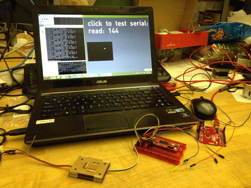
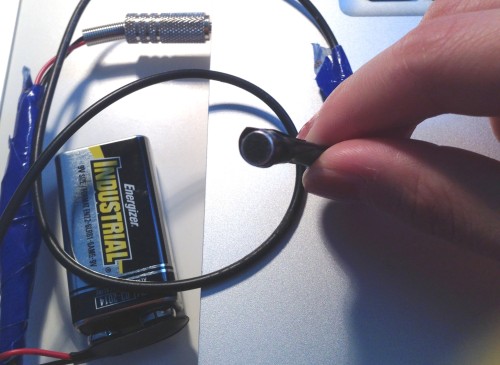
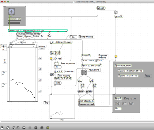
Breath Sensor: for now I’m still unable to find any off-the-shelf one which can differentiate between inhale and exhale. Hence I went to the approach using homemade microphone to get audio and using Tristan Jehan‘s analyzer object with which I found the main difference of exhale and inhale is the brightness. Nice thing about using microphone is that I can also easily get the amplitude of the breath which is indicating the velocity of the breath.  Problem with this method is it needs threshold calibration each time you change the environment and homemade mic seems to be moody – unstable performance with battery..

mini-mic

breath

Breath Sensor from kaikai on Vimeo.

Muscle Sensor:  It works great on bicep although I don’t have big ones but the readings on face is subtle – it’s only effective for big facial expressions – face yoga worked. It also works for smiling, opening mouth, and also frowning (if you place the electrodes just right). During the experimentation, I figure it’s not quite a comfortable experience having sticky electrodes on your face but alternatives like stretching fabric + conductive fabric could possibly solve the problem which is my next step. Also, readings don’t really differentiate each other, meaning you won’t know if it’s opening mouth or smiling by just looking at the single reading. Either more collecting points need to be added, or it could be coupled with faceOSC which I think is more likely the way I’m going to approach.

EMG_faces

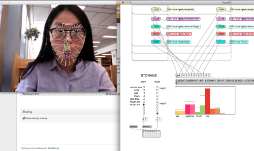
FaceOSC: I recorded several facial expressions and compared the value arrays. The results show that the mouth width, jaw and nostrils turned out to be the most reactive variables. It doesn’t perform very well with the face yoga faces but it does better job on differentiating expressions since it offers you more parameters to take reference of.

faceOSC_faces

Next step for me is to keep playing around with the sensors, try to figure out a more stable sensor solution (organic combination use) and put them together into one compact system.

Final Project Milestone #1: Liang

Assignment,Final Project,Hardware,Sensors — lianghe @ 5:21 am

Project: Tapo

Tapo is a tangible device encouraging people to create beats and perform percussion music with daily cups. What kind of beats it can produce? The volume of the liquid in the cup, the material of the cup and how people interact with the cup matter. The pitch and the timbre depend on the resonant property and the material of the cup. People’s gesture decides the speed or the pattern of the beat.

In the past one and a half week I accomplished every items listed for my first milestone.

1. System Design: I sketched the whole system design and labeled every component in the sketch.

system


2. Basic Diagram: Based on the system design, I finished the system diagram.

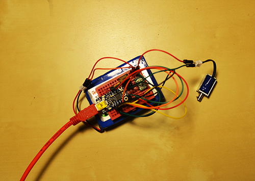
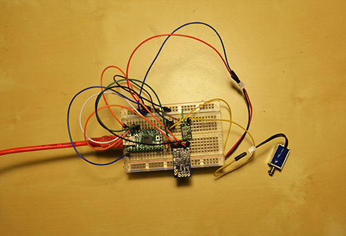
3. Quick Prototype: I have finished two prototypes so far. One is composed of a Trinket, a 1K resistor, a step-up regulator, a transistor (TIP 120), an accelerometer, a solenoid and a battery. The other one is different from this one by using a Teensy and a smaller transistor (FU3910) instead. These two prototypes are currently supported by a big battery set and USB power supply. In the final version I will replace by two separate batteries supporting the micro controller and the solenoid, also use all the tiny components in one enclosure. The Trinket version almost has the final look of this project except for the transistor and the batteries. However, the cheap board Trinket does support the Serial debug. Therefore, I built the second prototype by Teensy for the next phase: gesture’s detection with accelerometer.

milestone_pic1

Prototype 1

milestone_2

Prototype 2

The prototype 1 is implemented to test the solenoid and the prototype 2 combines solenoid and accelerometer, which converts the data of accelerometer into the speed of the solenoid. Both prototypes are testified that solenoid, accelerometer and the entire hardware configuration can work.

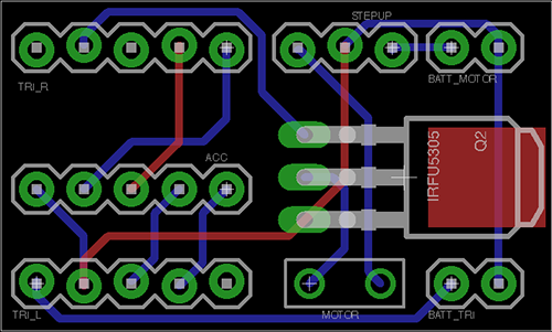
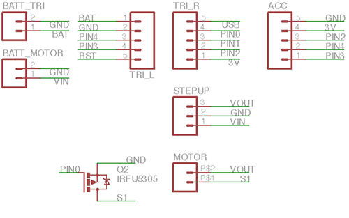
4. Circuit Design: In order to produce multiple devices, I customised a PCB board for all the hardware components, including batteries ports, solenoid interface, transistor, resistor, step-up regulator, and accelerometer.

PCB_final PCB_Schematics


5. Component Purchase: I did a research on every component I would use in this project and test several transistors and boards, listed a budget for the hardware that I need. I have all the parts at hand for just one prototype. Here is some links of my wanted components:

Trinket: www.adafruit.com/products/1500

Batteries: www.amazon.com/gp/product/B006N2CQSS/ref=oh_details_o00_s00_i00?ie=UTF8&psc=1

www.adafruit.com/products/1570

Solenoid: https://www.sparkfun.com/products/11015

Next Page »
This work is licensed under a Creative Commons Attribution-Noncommercial-Share Alike 3.0 Unported License.
(c) 2024 Hybrid Instrument Building 2014 | powered by WordPress with Barecity