Group Project: Multi-Channel Sound System (part 2)

Uncategorized — rkotcher @ 11:51 pm

8

Introduction:
The multi-channel sound system group is implementing a spatial instrument that allows us to interactively experience sound in space. The system includes software that controls a set of eight (currently) speakers that are positioned in space. We have two hardware setups for our project: the first is an umbrella that the speakers are mounted on, in which the listener sits beneath. The second is a wooden disk that is suspended from the ceiling. This setup allows the user to spin freely between the speakers.


Our three experiences are listed below:


Suspended Motion II


We have improved on the existing Suspended Motion project by incorporating our eight channel setup. Images from this new setup can be seen below. We are also still in the process of finding a chair that optimizes the experience. Many of the chairs we have tried are noisy or do not spin as freely as we would like. A complete description of the Suspended Motion setup and experience can be found here: teach.alimomeni.net/2013fall2/?p=2559.
67


Localization Sensitivity Experiment

This experiment involves using the eight speaker setup to test our hearing sensitivity. We start with slow impulses rotating around the circle, and these impulses gradually accelerate until it’s difficult to distinguish which direction the sound is coming from at any given instance.
32


Sonic Sculptures


In Sonic Sculptures, the user is immersed in a sound environment that they quickly discover they can manipulate with their gestures. They learn to interact with the environment to make a new composition, or they can sit and listen to their environment objectively. We’re currently using iPhone gyroscope, accelerometer, and compass data, and are also looking into using kinect data.
1


Implementing a STABLE and ROBUST system for practical use:

In both of our setups, we have tried to make our system robust enough to take out on the road! We’ve made acrylic enclosures for all the speakers, as well as designed an acrylic amplifier box which houses an amplifier array along with a charging circuit and a Li-ion battery. The battery powered amp-box gives us the mobility we’d like to make use of later. All wiring and circuits have been shifted from the breadboard to stripboard/veroboard and everything has been kept modular to allow quick assemble/dis-assembly. For the disk setup, all hardware is mounted onto a flat wooden surface as shown in the pictures above. Finally, shielded speaker wires were used to avoid any cross-talk.


Group Members:
M Haris Usmani (Persistent Member)
Robert Kotcher
Haochuan Liu
Liang He
Meng Shi
Wanfang Diao
Jake Berntsen

Group Project: Wireless Data + Wireless Video System (part 2)

Arduino,Assignment,Hardware,Max,OpenCV,Submission — jmarsico @ 11:07 pm

Overview

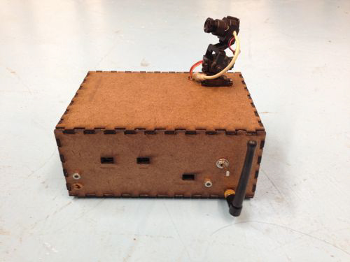
This project combines a Wixel wireless data system, servos, microcontrollers and wireless analog video in a small, custom-built box to provide wireless video with  remote viewfinding control.

IMG_0052-2


Hardware

Camera-Box:

  • Wixel wireless module
  • Teensey 2.0 (code found HERE)
  • Wireless video transmitter
  • 3.3v servo (2x)
  • FatShark analog video camera
  • 12v NiMH battery
  • 9v battery
  • 3.7v LiPo battery
  • Adafruit LiPo USB charger

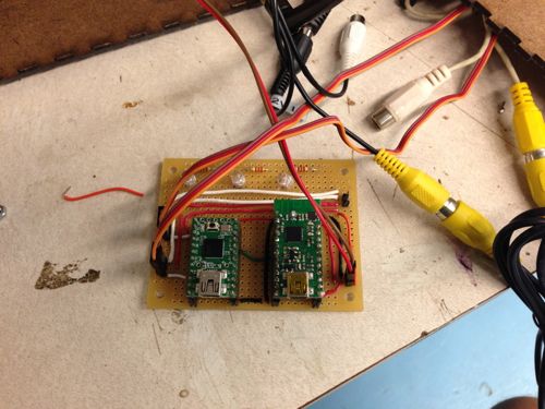
IMG_0048


Control Side:

  • Alpha wireless video receiver
  • Analog to Digital video converter (ImagingSource DFG firewire module)
  • Wixel Wireless unit
  • Max/MSP (patch found HERE)


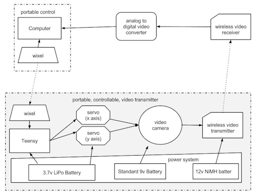
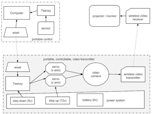
System Diagram:

wireless_servo_camera-2


Tips and Gotchas:

1. Max/MSP Patch Setup:

  1. Connect the your preferred video ADC to your computer
  2. Open the patch
  3. hit the “getvdevlist” message box , select your ADC in the drop-down menu
  4. hit the “getinputlist” message box, select the correct input option (if there are multiple on your unit)
  5. if you see ““NO SIGNALS” in the max patch:
  • double check the cables… this is a  problem with older analog video
  • verify that the camera and wireless transmitter are powered at the correct voltage

2. Power Choices:

  1. We ended up using three power sources within the box. This isn’t ideal, but we found that power requirement for the major components (teensey, wixel, transmitter, camera) are somewhat particular.  Also keep in mind that the video transmitter is the largest power consumer at  around 300mA.


 Applications:


1. Face Detection and 2. Blob Tracking


Using the cv.jit suite of objects, we built a patch that pulls in the wireless video feed from the box and uses openCV’s face detection capabilities to identify people’s faces. The same patch also uses openCV’s background removal and blob tracking functions to follow blob movement in the video feed.

Future projects can use this capability to send movement data to the camera servos once a face was detected, either to center the person’s face in the frame, or to look away as if it were shy.

We can also use the blob tracking data to adjust playback speed or signal processing parameters for the delayed video installation mentioned in the first part of this project.


3. Handheld Control

IMG_0065-2


In an effort to increase the mobility and potential covertness of the project, we also developed a handheld control device that could fit in a user’s pocket. The device uses the same Wixel technology as the computer-based controls, but is battery operated and contains its own microcontroller.

Group Project: OSC “Ground Control” (part 2)

Assignment,Max,Software,Submission — Can Ozbay @ 10:16 pm

Ground Control ?

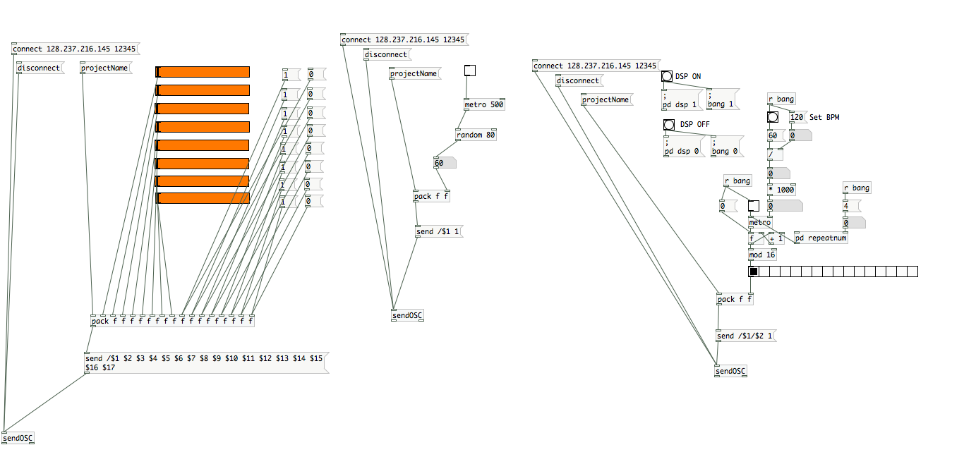
I’ve been tasked to design a central control panel for all the instruments that are being built during the course. Naturally, I wanted to be platform and software-license independent, and I picked PureData as a base platform, for everyone to be able to install and use it on their computers. So it can be compiled into an app, and can be deployed rapidly on any computer in minutes and it’s as reliable as the Wi-Fi connection of the computer.

Every project utilizes OSC somehow, however even with a standardized protocol like OSC, in order to control all projects from one central control panel, all projects needed a common ground. This is where Ground Control comes in.

Screen Shot 2013-09-30 at 8.35.26 PM

Essentially it is a collection of PD patches I’ve created, but they can work harmoniously together.

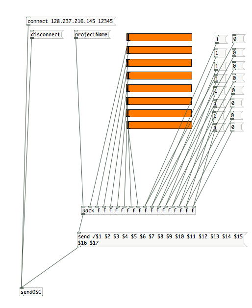
8 Channel Faders / Switches

Screen Shot 2013-09-30 at 8.33.57 PM


Assuming some projects would have both variable inputs and on/off switches, I made this patch to control  8 faders, and 8 switches. Although it’s infinitely expandable, current photo shows only 8 objects.

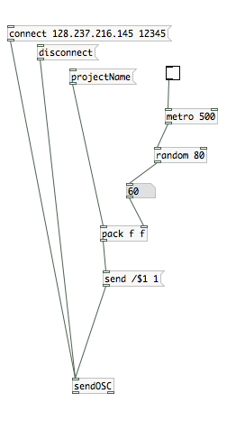
Randomness

Screen Shot 2013-09-30 at 8.34.05 PMConsidering many people are working on an instrument, and these instruments are extraordinary hybrid instruments, I thought the control mechanism could benefit from having some level of randomness in it. This patch can generate random numbers every X seconds, in a selected number range, and send this data do the instrument. An example usage would be to control odd electrical devices in a random order.


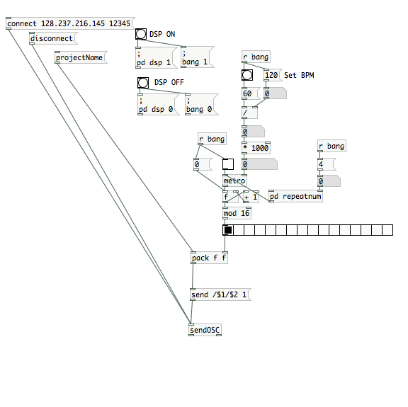
Sequencer

Screen Shot 2013-09-30 at 8.34.28 PM

Making hybrid instruments is no fun, if computers are not being extra-helpful. I thought a step sequencer could dramatically improve some hybrid instruments by adding a time management mechanism. Using this cameras can be turned on and off for selective periods, specific speakers can be notated/coordinated or devices can be turned on/off in an orchestrated fashion.


Group Project: Multi-Channel analog video recording system (part 2)

Arduino,Assignment,Submission — mauricio.contreras @ 2:17 pm

Overview

Eight video cameras present eight different views into a dynamic world. They can be oriented a number of ways including inward or outward on a subject.

Our basic setup is a box with the eight cameras arranged along the top. Cables run from the cameras to the base of the box where they are connected to power sources and a video multiplexer. The base also contains an Arduino which is used to control the mux. Power for the mux is supplied via the Arduino. A basic diagram of this setup can be seen below (this setup matches our “Fat Shark” application, as described in this post, but also can be generalized).

Hardware Details

Cameras

These cameras are generic analog mini cameras you can buy on the internet or steal from the artfab lab. They can be fed with 9-12V, and are provided with a 3 conductor cable: V+, GND and video.


Camera boxes

The camera boxes were constructed out of MDF. There is nothing special about the design except that there are holes to allow the camera to poke out as well as for the cord to come in. A good place to create a box is here: boxmaker.rahulbotics.com/.
Our camera cords are secured inside by foam padding and a zip-tie.


Open-beam structure

Open beam is very structural. openbeamusa.com/


Cords

Each camera has power input and video output. We used three 1-to-4 power splitters to distribute  power from a single 9V source to the 8 cameras and other components. The video output eventually terminates as RCA to connect to the video MUX.


Mux

The mux takes 8 analog video inputs, a selector input, an enable input, a power source, and 1 analog video output. This board is a collaboration between Ray Kampmeier and Ali Momeni, and more information can be found here www.raykampmeier.net


Arduino

The arduino controls the mux selector from either being programmed to switch channels or by an external controller eg a computer or a phone outputting OSC. Any arduino would do.


Immersion RC

The video output can be routed to a sender antenna that takes in a video input and power. Their website is: www.immersionrc.com


Fat Shark

The goggles with screens inside: www.fatshark.com


Code

All our code and documentation is located on github github.com/sbarton272/VideoMux.

Looking Outwards: Fat Shark

As shown in the diagram, the video multiplexer is connected to the immersion RC chip that sends a radio signal to the Fat Shark, where a single output video appears through the goggles. Fat Shark is a very interesting device because it allows you to see videos and images that are not necessarily where you can traditionally view. As of now, the cameras are fixed in place on the Open-beam structure. The structure is robust enough for mobility, which allows for a wide range of possibilities on the location of the system.

Looking Inwards

The setup of the cameras allows us to rotate the cameras inwards. For this application, we place an object in the middle, and use the eight cameras to view it from different angles. In order to hold the object in place, we cut out a square piece of masonite, that is placed on top of four screws and can be moved up and down depending on the size of the object. Similar to the Looking Outwards application, the videos are controlled by the phone through touchOSC.

Third Application

We took the outward facing camera set-up and did a few shoots using our new compass controller. Here are the results:

Experiment 1:


Experiment 2:


Fourth Application: An Image Capture System for 8 Cameras with Different Angles.

The aim of this project is building a image capture system with our camera box for 8 cameras. The capture system is composed by a real time processing software : Pure Data and Open source hardware platform : Arduino. Function is simple like that first, we made a connection between a video multiplexer and arduino, so we can control and choose which camera and angle we want to use. And, in Pure data patch for this combination (Arduino  and Video multiplexer), we can use a user interface which help to choose which camera with GUI and make a captured and file-saved images into PC. And then, we can use these images for making 3D scan image and multi viewed photo like a panorama image.

test


Group members

  • Mauricio Contreras
  • Spencer Barton
  • Patra Virasathienpornkul
  • Sean Lee
  • JaeWook Lee
  • David Lu

Toward understanding human-computer interaction in composing the instrument (Fiebrink et al)

Instrument,Reference,Theory — rkotcher @ 5:41 pm

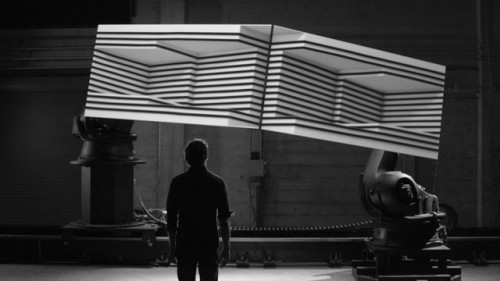
Instrument: “Box” by Bot & Dolly (2013)

Instrument,Reference,Uncategorized — cwilliams @ 2:24 pm

box_by_bot_and_dolly

More

Instrument: “Box” by Bot & Dolly (2013)

Instrument,Reference — David Lu @ 11:44 pm

You should really watch this.

More…

Group Project: “Introducing OSC, with CollabJazz” by Robert Kotcher & Can Ozbay (part 1)

Assignment — Can Ozbay @ 6:28 pm

Project Description
Our assignment was to showcase how OSC can be used to remote control/connect media objects, or computers together. After an hour of brainstorming, we’ve decided to build a collaborative jazz drumkit, with pureData, and implemented the following control parameters :

  • HH, Snare, Kick Volume & Texture controls,
  • Cutoff Frequency & Q controls,
  • Business & Swing intensity controls.

We’ve added 13 different parameters in total and made a universally controlled jazz drum machine.

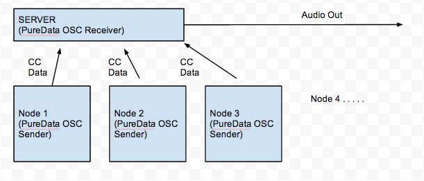
Later, we wrote a client app also in PureData, which can be installed on all 13 users’ computers to control the parameters we’ve created. More ? In the video.

Connectivity Diagram

Screen Shot 2013-09-23 at 6.24.15 PM

Potential Possible Ideas

This system can be used to create a cumulative rhythm by a jazz orchestra, or an electronic music ensemble to control the overall speed of the current track.

Another great application would be online collaborative rhythm exercises.

Also the system could be easily integrated into DAW software, and it could essentially enable an entire band to work on a single project.

Problems needed to be addressed

Currently, with this system, the nodes can only talk to the server, and the server is the sound output. However the system can be improved to provide two way connection, and this would dramatically improve the capabilities of the system. Ex: Server sending current volume data to everyone.

Also, for if it had to be implemented for a Jazz improv orchestra, it would require the entire band to have control over the tempo, not just one node. Although this is easy to implement, with our prototype, all we wanted to do was to try and create an experimental drum machine.

Group Project: Wireless Data + Wireless Video System (part 1)

Uncategorized — jmarsico @ 5:51 pm


Idea Proposals: 

1. Interactive Ceiling Robot

Wireless => Portability. To showcase the substantial reach of wireless control, a robot with a camera on a high ceiling, interacts with persons beneath it. The robot move around in the high shadows, feeding video of the ground below in various directions. When no person is underneath to robot releases a small ball of yarn/ candy bar on string just above ground level, enticing those beneath to it. As soon as movement is detect/ person goes for the bait, the robot reels the bait back in out of reach. The video feed capture the person dismay and distraught. Repeats process.

The ceil is a new frontier, ofter unexpected and unnoticed. A robot, supposedly a machine subservient to human, now turns the tables and mocks them from its noble high perch. From above it claim a birds-eye view, supposedly monitoring like big brother or looking down upon those beneath. A reverse of power structure.

Possible robustness factor will be a versatile clamping mechanism that easy hook on to various pipe or structural supports along the ceiling. Possible internal cushioning in case of falls. Wireless controlled camera with easy to use user interface.

2. “Re-Enter”

We will place the wireless video system near an entrance and record people walking into a building. Inside the building a delayed playback of that video will be projected elsewhere in the building, near the entrance. Some visitors, who happen to travel past the playback location, will possibly see a video of themselves entering the building in the past. The project is a mobile version of Dan Graham’s “Time Delay Room“. Users will be able to affect the playback time and angle of the camera.

The project aims to confuse visitors just enough to stop their quick routine.  By introducing the possibility of seeing a moving image of themselves, visitors are forced to contemplate their current and near-past action. This team, built of mechanical and electrical engineers, artists and A/V experts, is well equipped to take on the challenges presented by this project, including confronting their fast-paced schedules.

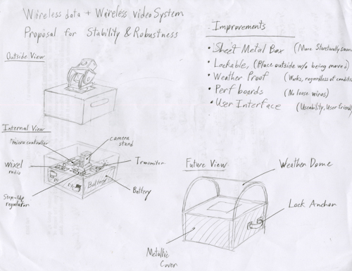
A main challenge of this proposal will be to build a wireless video transmitter that can handle outdoor weather and be secured against theft. See drawings below for proposed changes. To deal with weather, the team will build a temporary vestibule to sheild it from rain and wind. To prevent theft, the team will include anchor points on the wireless box that can be used to lock it to a permanent structure nearby.

3. yelling robot

we will fix this portable camera on a vehicle with four wheels and place two sensors to capture the applause sound from the opposite direction. Initially, the people will be divided into two groups and the vehicle will be put in the middle initially; then this little vehicle will move toward to the group has larger applause sound and keep to capture the faces of winning group at the same time.

this project aims to simulate the competing between two groups. It’s like a wireless edition of pull-push game. Since the projector will display the winning group, the other group may try their best to get the focus of projection image so that they will make better interactions to make larger sound.

The main challenge may be that how to capture the winning group’s faces and adjust the angle of camera since it approaches the winning group back and forth.


Block Diagram of System
wireless_servo_camera

Diagram of improved, more robust, weatherproof box:
scan004


participants: Job Bedford, Chris Williams, Ziyun Peng, Ding Xu, Jake Marsico

Group Project: Multi-Channel analog video recording system (part 1)

Arduino,Assignment,Submission — mauricio.contreras @ 5:31 pm

The project is centered around an 8-to-1 analog video multiplexer board. This board is a collaboration between Ray Kampmeier and Ali Momeni, and more information can be found here.

In the present setup, 8 analog small video cameras (“surveillance” type) are connected as inputs to the board, and the output is connected to a monitor. The selection of which of the 8 inputs gets routed to the output is done by an Arduino, which in turn maps the input of a distance sensor to a value between 1 and 8. Thus, one can cycle through the cameras simply by placing an object at a certain distance of the sensor. The connection diagram can be seen below:

A picture of the board with 8 inputs is displayed below (note the RCA connectors):

Video Multiplexer board

The original setup built for showcasing the project uses a box shaped cardboard structure to hold a camera in each of its corners, with the cameras pointing at the center of the box (see below).
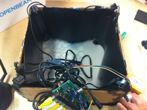
Initial setup for 8 cameras

A simple “shield” board was designed to facilitate the interface between the Arduino, the distance sensor and the video mux.
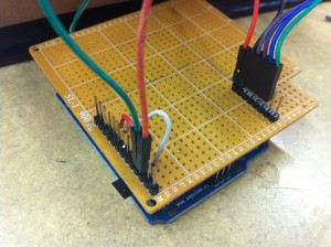
Arduino shield

Improvements

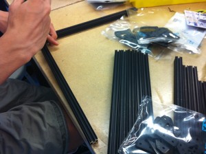
The current camera frame is of cardboard which is not the most robust of materials. A new frame will be constructed of aluminum bars assembled in a strong cube:2013-09-21 22.17.04 

This is the cube being assembled:

2013-09-20 15.22.04

Wires attachments for the cameras will be routed away from the box to a board for further processing.

Project Ideas

1) Jigsaw faces

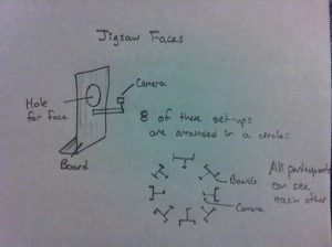
Our faces hold a universal language. We propose combining the faces of eight people to create a universal face. Eight cameras are set-up with one per person. The participants place their face through a hole in a board so that the camera only sees the face. These set-ups are arranged in a circle so that all the participants can see each other. The eight faces are taped and a section of face is selected from each person to combine into one jigsaw face. This jigsaw face is projected so that the participants can see it. This completes the feedback loop. The jigsaw face updates in real time so as the participants share an experience their individual expressions combine in the jigsaw face.

The Jigsaw Face  will consist of a few boards (of wood) for people to put their face through. Each board will have a camera attachment and all the cameras will be attached to a central processor. The boards will be arranged so that people face each other across a circle. This will enable feedback among the participants.
2013-09-21 22.17.18

2) The well of time : Time traveling instrument

I’m still thinking about the meaning of 8 cameras and why we need and what we can do originally. And, I assume that 8 cameras mean 8 different views and also it could be 8 different time points distinguishably. After arriving this point, I realized we can suggest a moment and situation that is a mixed timezone and image with a user’s present image from each camera and the old photo from in the past which is triggered by a motion or distance sensor, attached with each camera.

Here is a sample image of my thought. This image contains the moment of now and the past time when the computer science building had constructed.
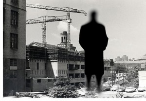
sean1_500

And, if a user stand with another camera, we could represent the image like below. The moment of first introducing the propeller steam boat. basically, this is the artistic way of time traveling. So, our limitation by black and white camera couldn’t be problem and in this case, it could be benefit.
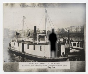
sean2-500

For this idea, of course, we have to make some situation and installation looks like this.

sean3_500


More precisely, it has this kind of structure.
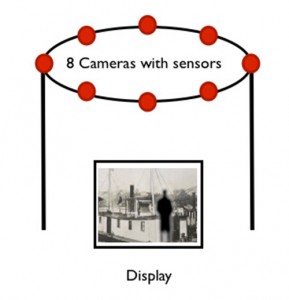
sean4-500
As a result, an example interaction scenarios with a user and diagram.
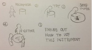
sean5-500
sean6_500

3) Object interventions

Face and body expressions can tell a lot about people and their feelings towards the surroundings or the objects of interaction. Imagine attaching eight cameras to a handheld object or a large sculpture. With eight cameras as the inputs, the one output will be the video from the camera that is activated by a person interacting with it in that specific area. The object can range from a small handheld object like a rubik’s cube, to a large sculpture at a playground. We think it will be very interesting to see the changes in face and body expressions as a person gets more (or less) comfortable with the object. It might be more interesting to hide these cameras so that the user will be less conscious of their expressions because they do not realize they are being filmed. It will be more difficult to do that with a large public sculpture, but we can do a prototype of a handheld object where we can design specific places where the cameras should locate so that they cannot be seen.

4) Body attachment

When we see the world we see it from our eyes. Why not view the world from our feet. Perceptions can change with a simple change in vantage point. We propose to place cameras on key body locations: feet, elbows, knees and hands in order to view the world from a new vantage point as we interact with our surroundings. Cameras would be attached via elastic and wires routed to a backpack for processing.

Group members:

  • Mauricio Contreras
  • Spencer Barton
  • Patra Virasathienpornkul
  • Sean Lee
  • JaeWook Lee
  • David Lu
Next Page »
This work is licensed under a Creative Commons Attribution-Noncommercial-Share Alike 3.0 Unported License.
(c) 2025 Hybrid Instrument Building 2014 | powered by WordPress with Barecity