Final Project “TAPO”: Liang

TAPO: Speak Rhythms Everywhere

Idea Evolution:

This project comes from the original idea that people can make rhythms through the resonant property and material of cups and interacting with cups. However, as the project progresses, it is more interesting and proper for people to input the rhythms by speaking than do gestures on cups. It also extends the context from cups to any surface because of the fact that each object has resonant property and specific material. So, the final design and function of TAPO have a significant change from the very raw idea. The new story here is:

“Physical objects have resonance property and specific material. Tap object gives different sound feedback and percussion experience. People are used to making rhythms by beating objects. So, why not provide a tangible way not only allowing people to make rhythms with physical objects around she/he, but also enriching the experience by some computational methods. The ultimate goal for this project is that ordinary people can make and play rhythms with everyday objects, even perform a piece of percussion performance.”

Design & Key Features:

TAPO is an autonomous device that generates rhythms according to people’s input (speech, tapping, making noise). TAPO can be placed on different surfaces, like desk, paper, ground, wall, window… With different material and the object’s resonant property, it is able to create different quality of sound. People’s input gives the pattern of rhythm.

System diagram

a) voice, noise, oral rhythm, beat, kick, knock, oral expression… can be the user input

b) using photo resistor to trigger recording

c) get rid of accelerometer, add led to indicate the state of recording and rhythm play

Hardware

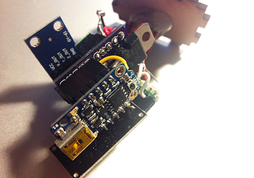
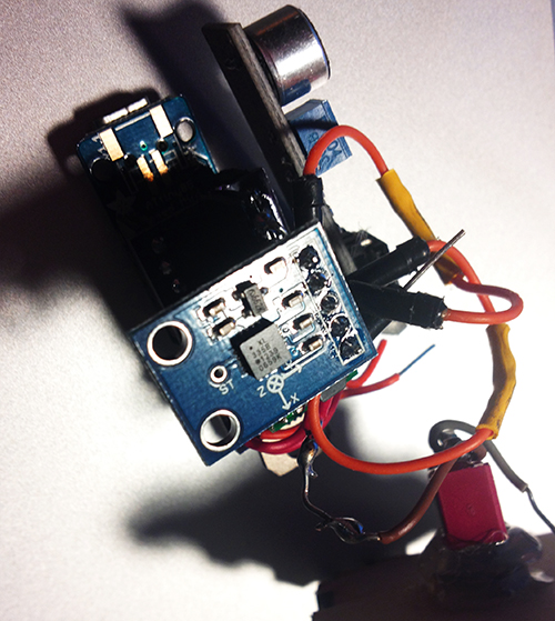
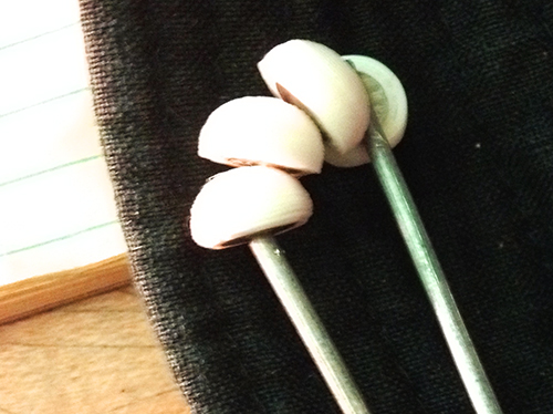
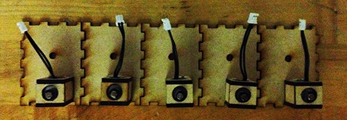
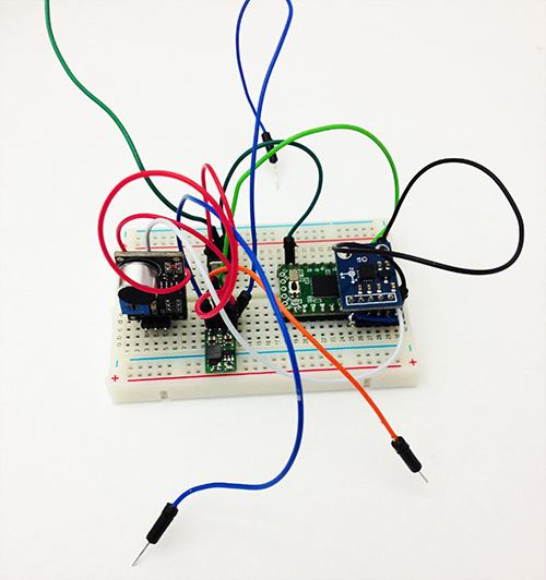
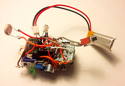
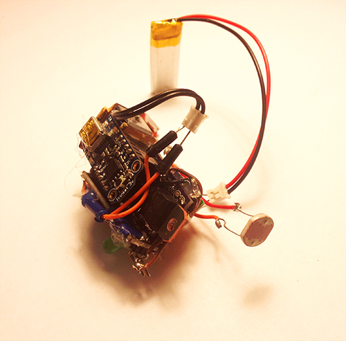
It is composed of several hardware components: a solenoid, a microphone electret, a transistor, a step-up voltage regulator, a Trinket board, a colourful LED, a photocell, a switch and a battery.

photo1


photo2


Fabrication

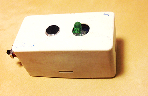
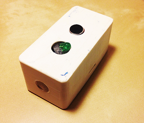
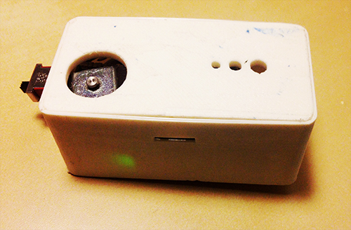
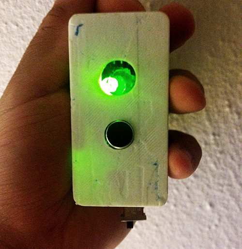
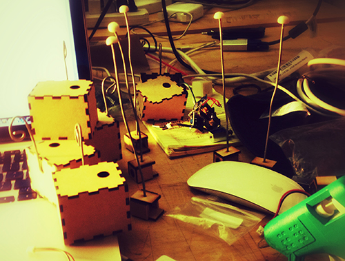
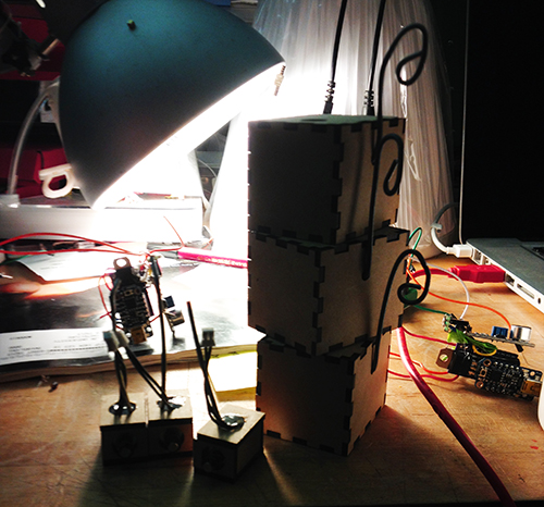
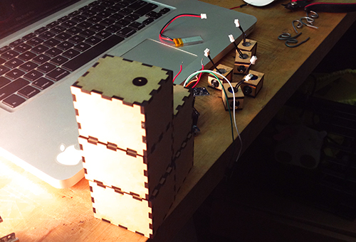
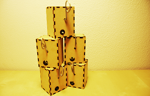
I used 3D printing enclosure to package all parts together. The holes with different sizes on the bottom are used for different usage, people can mount a hook or a suction. With these extra tools, it can be places on any surfaces. The other big hole is used for solenoid to beat the surface. The two holes on the top  side are used to show microphone and LED light separately. On each side, there is a hole for photo resistor and switch.

photo3 photo4

TAPO finally looks like this:

photo6 photo5 photo7 photo8 photo9

Demostration:

Final introduction video:

Conclusion & Future Work:

This project gives me a lot more than technology. I learn about how to design and develop a thing from a very raw idea, and keeping thinking about its value, target users, and possible scenarios in a quick and iterative process. I really enjoy the critique session, even though it is tough and sometimes makes me feel disappointed. The positive suggestions are always right and lead me to a high level and more correct direction. I realise my problems on motivation, design, and stroytelling from these communications. Fortunately, it gets much more reasonable from design thinking to value demonstration. I feel better when I find something more valuable and reasonable comes up in my mind. It also teaches me the significance of demonstrating my work when it is hard to describe and explain. In the public show on Dec. 6th, I found people would like to play with TAPO and try different inputs, they are curious about what kind of rhythm TAPO could generate. In the following weeks, I will refine the hardware design and rich the output (some control and digital outputs).

Acknowledge:

I would like to thank very much Ali Momeni for his advices and support on technology and idea development, and all the guest reviewers who gave me many constructive suggestions.
Final Presentation – Spencer Barton

The Black Box

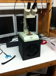
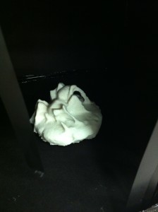
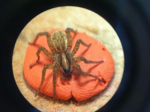
Put your hand into the black box. Inside you will find something to feel. Now take a look through the microscope. What do you feel? What do you see?

The Box and Microscope

2013-11-19 20.00.16

Inside the Box

2013-11-19 19.43.03

Under the Microscope

2013-11-17 00.03.12

When we interact with small objects we cannot feel them. I can hold the spider but I cannot feel it. The goal here is to enable you to feel the spider, to hold it in your hand. Our normal interaction with small things is in 2D. We see through photographs or a lens. Now I can experience the spider though touch and feel its detail. I have not created caricatures of spiders, I copied a real one. There is loss of detail but the overall form is recreated and speaks to the complexity of living organisms at a scale that is hard to appreciate.

The box enables the exploration of the spider model before the unveiling of the real spider under the microscope. The box can sense the presence of a hand and after a short delay, enabling the viewer to get a good feel of the model, a light is turned on to reveal the spider under the microscope.

Explanation of the Set-up

The Evolution of Ideas

As I created the models I found that my original goal of recreation was falling short. Instead of perfect representations of the creatures under the microscope, I had white plastic models that looked fairly abstract. The 123D models were much more realistic representations because of their color. My original presentation ideas focused around this loss of detail and the limits of the technology. However, what I came to realize was were the strengths of the technology lay: the recreation of the basic form of the object at a larger scale. For example someone could hold the spider model and get a sense of abdomen versus leg size. Rather then let someone view the model I decided to only let them feel the model.

Feedback and Moving Forward

The general feedback that I got was to explore the experience of the black box in more depth. There were two key faults with the current set-up. First the exposure of the bug under the microscope happened too soon. Time is needed for the viewer to form a questions of what is inside the black box. Only after that question is created should the answer be shown under the microscope. The experience in the box could also be augmented. The groping hand inside the box could also be exposed to other touch sensations, it could activate sound or trigger further actions. The goal would be to lead the experience toward the unveiling. For example sounds of scuttling could be triggered for the spider model.

The second piece of feedback lay with the models themselves. First it was tough to tell that the model in the box was an exact replica of the bug under the microscope. The capture process losses detail and the model creation through 3D printing adds new textures. The plastic 3D models in particular were not as interesting to touch as the experience was akin to playing with a plastic toy.

To recognize and rectify these concerns this project can be improved in a few directions. First I will improve the box with audio and a longer exposure time. Rather then look through the microscope I will have a laptop that displays the actual images that were used to make the model. The user’s view on this model with then be controlled by how they have rotated the model inside the box.

I will try another microscope and different background colors to experiment with the capture process and hopefully improve accuracy. I will redo the model slightly larger with the CNC. MDF promises to be a less distracting material to touch. Additionally the fuzziness of MDF is closer to the texture of a hairy spider.

Final Project Milestone #3: Liang

Final Project,Laser Cutter,Rhino3D,Sensors — lianghe @ 2:23 am

1. My boards arrived!!

After about 12 days, OSH Park fabricated and delivered my boards. Yes, they are fantastic purple and look like exactly what I expect. I soldered and assembled every components together to test the board. Finally, all boards work with all the components but the transistor. I used smaller one instead of TIP 120. For some reason, it could work with Trinket board. So, I used TIP 120 again with my final board.

photo


2. Add Microphone Module!

To solve the problem of gestures and how user interacts with cup and Tapo, I decided to use a microphone to record user’s input (oral rhythm, voice, and even speech). The idea is quite simple: since the electret microphone turns analog voice data into digital signal, I can just make use of the received signal and generate certain beat for a rhythm. That is more reasonable interaction for users and my gestures can be put into two categories: trigger the recording and clear the recorded rhythm. The image below shows the final look of the hardware part, including the PCB board, Trinket board, transistor, step-up voltage regulator, solenoid, accelerometer, electret microphone, and a switch.

photo

photo1


photo2


3. Fabrication!

All parts should be enclosed in a little case. At the beginning I was thinking of 3D printing a case and using magnets to fix the case on the cup. I 3D printed some buckets with magnet to see the magnetic power. It seemed not very well in attracting the whole case. The other thing looks difficult for 3D printing case was that it was not easy to put the entire hardware part in and get it out.

photo copy

Then I focused on laser cutting.  I created a box for each unit and drilled one hole for solenoid, one hole for microphone and a hole for hook. I experienced three versions: the first one left one hole for the wire of solenoid to go through, thereby connecting with the main board. But the solenoid could not be fixed quite well (I used strong steel wire to support it); The second version put the solenoid inside the box and opened a hole on the back facet, so that it could tap the cup it was mounted on, but the thickness of the box avoided the solenoid to touch object outside; In the final version I drilled a hole on the upper plate for the switch, and modified the construction for solenoid.

photo

photo copy


Version 1

photo copy

Version 2

photo copy

Solenoids

DSC_0110 copy1

Version 3

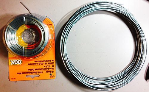
Another thing is the hook. I started with a thick and strong steel wire and resulted in that it could not be bended easily. Then I used a thinner and softer one, so that it could be bended to any shape as the user wished.

photo copy

4. Mesh up codes and test!!

Before program the final unit, I programmed and tested every part individually. The accelerometer and the gestures worked very well, the solenoid worked correctly, and I could record user’s voice by microphone and transferred it to certain pattern of beats. Then the challenge is how to make a right logic for all the things work together.  After several days’ programming, testing, debugging, I meshed up all logics together. The first problem I met was the configuration of Trinket, which led to my code could not be burned to the board. Then the sequence of different module messed up. Since the micro controller processed data and events in a serial sequence, so the gesture data could not be “timely” obtained while the beats of solenoid depended on several delays.

I built a similar circuit, in which my custom PCB was replaced by a breadboard, to test my code. In the test, I hoped to check if my parameters for the interval of every piece of rhythm was proper, if the data number of the gesture set was enough to recognise gestures, if specific operation causes specific events, and most importantly, if the result looked good and reasonable.

Here is the test unit:

photo copy

Here is a short video demo of the test:

Final Project Milestone 3 – Spencer Barton

3D Printer,Final Project,Instrument,Rhino3D,Scanning — spencer barton @ 8:47 pm

Model Making

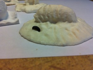
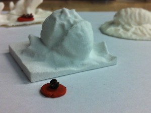
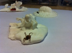
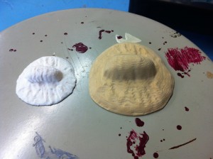
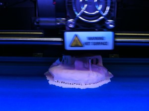
I have begun to create models. The current models utilize additive methods: one with plaster printing (thanks to dFab) and PLA printing with a Makerbot in Codelab. I also utilized the Art Fab CNC to make a slightly larger rolly polly. Some of the below models are shown with the original object that I used for the capture.

2013-11-17 17.53.01

2013-11-17 18.06.09

2013-11-17 17.55.04

2013-11-17 18.08.14

2013-11-23 13.54.47

2013-11-23 13.54.20

2013-11-18 22.59.09

Final Project Milestone 2 – Spencer Barton

Final Project,Rhino3D,Scanning — spencer barton @ 12:34 am

A Walk in the Woods

In the first milestone I defined five options for objects to capture. I decided to go with ‘A Walk in the Woods’:

I grew up playing in the woods. It was always an adventure – new bugs lay under every rock and dirt could be molded into innumerable forts. I have gradually left the woods behind (as I imagine most of us are doing these days). My goal is to take a simple walk through the woods and record any and all interesting discoveries that I make. These critters, rocks and leaves would then be created as physical models to capture some of that excitement of discovery.

Captures and Lessons Learned

I have performed a number of captures now, some with great success and others with less.

I have a few pointers for capture:

  • Lighting if important. Diffused light works better then a spotlight. Captures did well with just the microscope light on.
  • The angle of capture cannot be too deep. The objects did best at 30-45 degrees.
  • The object surroundings are very important as background objects help the software orient the images. Latter models all have orange clay bases for support and textured background.
  • 30x magnification worked well for the objects that I had. Captures work best when the capture can see a wide range of the object’s surroundings
  • Taking pictures at different focus depths came out well.
  • The more pictures the better. I usually took 40-70.
  • Shiny objects don’t do as well
  • Small details like bug legs are rarely captured.

Here are some of the results (all models available on my 123D account):

Future Steps

The next hurdle is manufacturing. I am exploring two options. One in 3D printing in plaster. The d-fab on campus has the ability to print color plaster models.

I am also looking into 123Dmake which converts designs to layered models which can then be cut in something like cardboard. This would enable me to create some very large models.

Final Project Proposal – Liang He

This work is licensed under a Creative Commons Attribution-Noncommercial-Share Alike 3.0 Unported License.
(c) 2024 Hybrid Instrument Building 2014 | powered by WordPress with Barecity