Final Project “ImSound”: Ding

Audio,Final Project,OpenCV — Ding Xu @ 9:31 pm

ImSound: Record/Find your sounds in images

We run into a lot of sounds in our lives and sometimes we will naturally come up with certain color with those sounds. We may even form a memory of our city or living environment with some interesting sounds and colors. As for me, when I listen to some fast and happy tempo I could sense a color of dark red and when I run into some soft music, I may feel it is green or blue. Different people may have different feeling about different sounds. Therefore, ImSound is a devices aiming to encourage people collecting useless sounds in lives, all kinds of noise for example, convert them to certain colors based on their understanding and play the similar mixed sounds when run into a new image. The process stems from sound to image and then to sound.

For the user himself/herself, this device may help him/her convert some useless or even annoying sounds into some interesting funny sounds and  find new information from it. As for others, this devices is like a business card of a user’s specific understanding about the world’s sounds and share to others.

Hardware improvement:

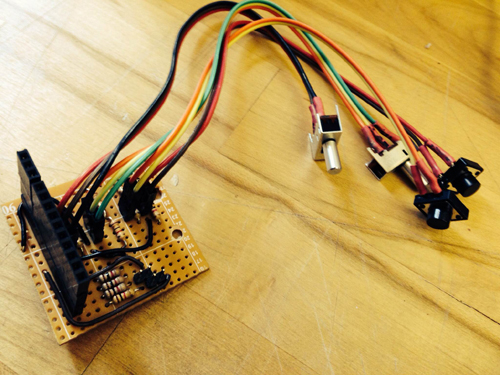
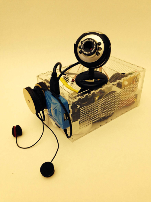
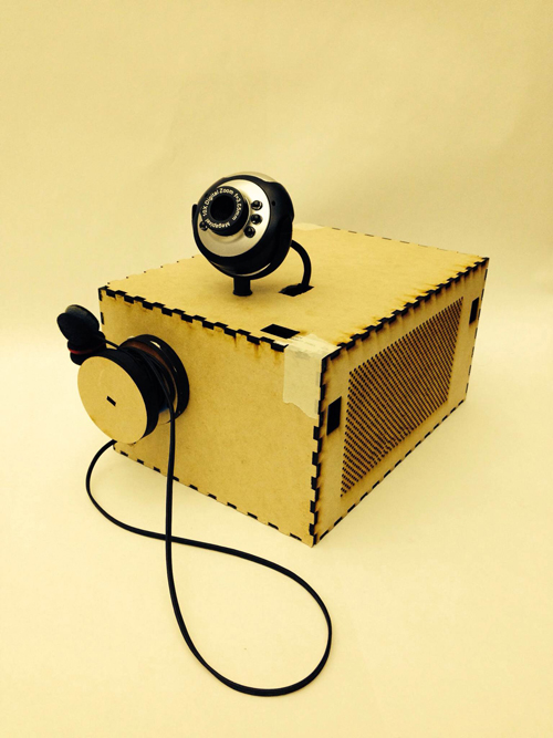
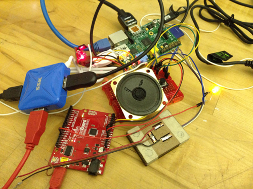
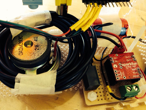
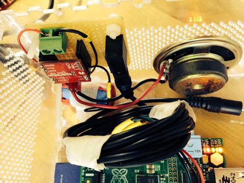
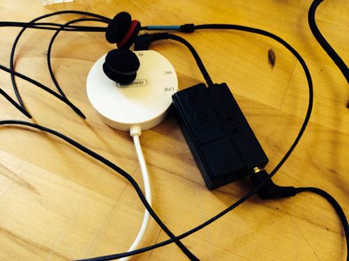
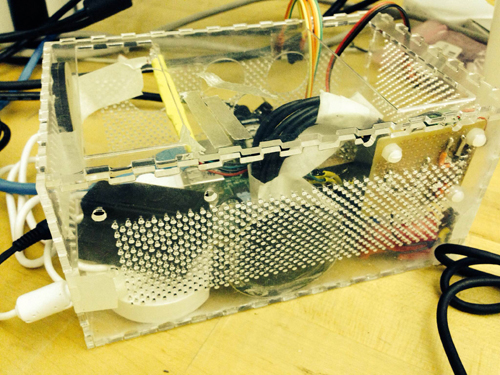
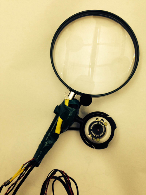
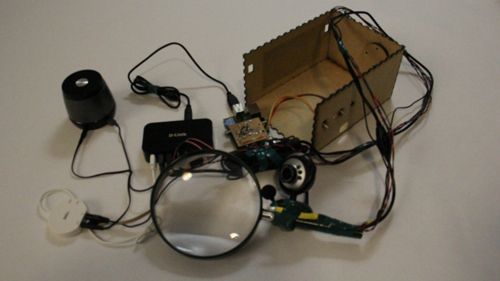
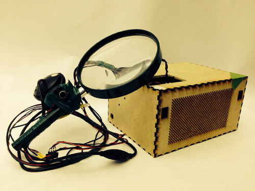
Based on last time’s feedback, people failed to get aware of the focus when capturing an image. Thus, in the final prototype, I use a magnifier attaching a camera and a mic as a portable capture device for people to focus where the sound and where they will capture an image, with a metaphor of finding sounds in our lives. Instead of several buttons to control the recording and taking image, a single push button in the handle of magnifier is used to trigger taking a photo and then automatically record a 3s sound.

Final1

Final3

Final2

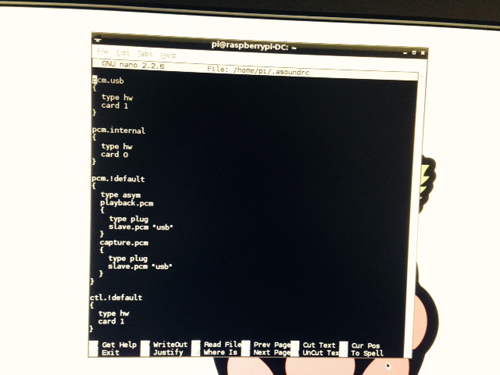
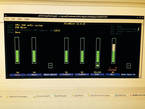
Software improvement:

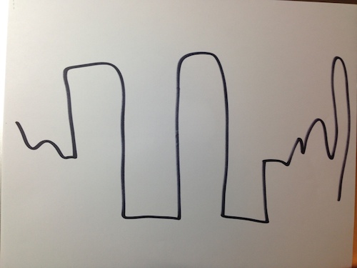
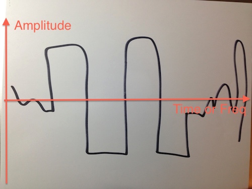
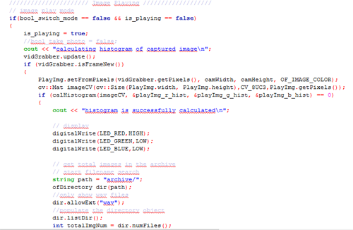
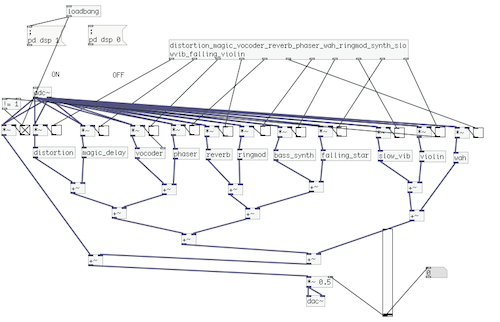
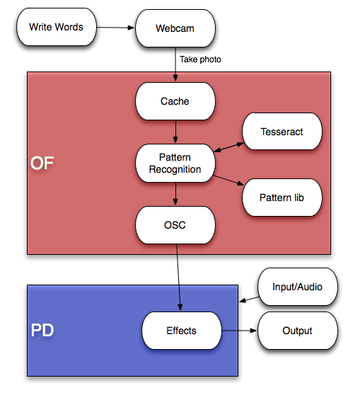
Instead of using the whole histogram of images, I converted the image from RGB to HSV and used the H value for histograms with 12 bins (variable). That is to say, the images will be divided into 12 clusters based on their major color. Each image is classified and the sound will be recorded into corresponding track contributing to the library of that color. That is to say, every color has a soundtrack which belong to this cluster. Then a granular analysis is used to divided the sound into small grains and remix them for a new sound of that class. When changing to the play mode, the H histogram is computed and the corresponding sound will be played.

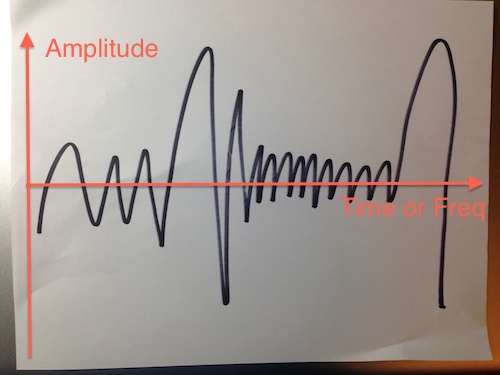
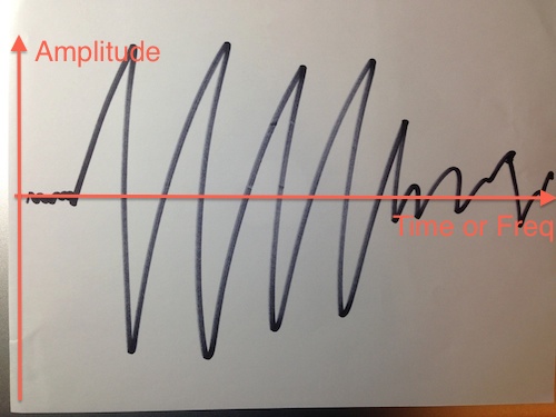
I used a OF ofxMaxim with FFT processing for granular analysis, but the output sound effect is not that good. The speed of sound is changed but without much similar grains connecting together. This is a main aspect I should improve for the next step of this project.

 Demo Video:

Future Plan:

1. the most important is to get more in-depth granular analysis to re-mix the sounds. My current thought is to combine the grains with their similarities among each other. The funny part is that with the growing of number of recording sounds, the output sound is dynamic changing and form some new sound.

2. Take some more actual image and sound to test the effects of whole process. Aiming to a specific type of sound may be a good choice, such as city noise.

Conclusion/Acknowledge:

Although this project is far from fully completion, I learned a lot in this process, not only the technologies such as RPI, openFrameworks and Linux; more importantly, I learned a lot about input/output design, mapping, and telling story (a point I did not do well). It teaches me to think why should we design this device and inspired me to think whom and where does a device will be used in my future projects. Thanks Ali Momeni very much for his suggestions and all the conversations during this whole process of project, and all the reviewers and classmates who help me to improve my ideas and project.


Audible Color by Momo Miyazaki, CIID

Audio,OpenCV,Reference — Ding Xu @ 9:06 pm

audible color from Momo Miyazaki on Vimeo.

Final Project Presentation — Haochuan Liu

Assignment,Audio,Final Project,OpenCV — haochuan @ 10:09 pm

Drawable Stompbox

Write down your one of your favorite guitar effects on a piece of paper, then play your guitar, you will get the sound what you’ve written down.

Here is the final diagram of this drawable stompbox:

Screenshot 2013-11-27 22.11.45


After you write down the effects on a piece of paper, the webcam which is above the paper will capture what you’ve written into a software written in openframeworks. The software will analysis the words and do the recognition using optical character recognition (OCR). When your write the right words, the software will tell puredata to turn on the specific effect through OSC, you will finally hear what you’ve written when you play your guitar.

The source code of this software can be found here.

Here is a demo of how this drawable stompbox works.

Feedback from my final presentation:

I have got a lot of good idea and advice for my drawable stompbox as below:

1. Currently writing down a word to get the effects has no relationship with ‘drawing’. It is more like a effect selection using word recognition.

2. I was thinking of drawing simple face on the paper instead of just boring words. How about using a webcam directly to scan real people’s face, getting their emotion on their face and then find the relationship between different faces and different effects.

3. Words recognition is so hard, for there are a lot of factors to make it doesn’t work well, such as the hand-writing, the resolution of the webcam and the light of environment.

Following work:

For the following weeks, I decide to make my instrument a real drawable stompbox. I will begin with a very simple modulation:

People can simply draw the ‘wave’ like this:

2013-11-27 23.03.24 2013-11-27 23.03.34 2013-11-27 23.03.43

From this drawing, it is easy to define and map the amplitude and the frequency.

2013-11-27 23.03.43 2013-11-27 23.03.34 2013-11-27 23.03.24


Then I will use the ‘wave’ from the drawing to do a modulation with the original guitar signal. People can draw different type of waves to try how the sound changes.


Final Project Milestone 3 – Ding Xu

Audio,Final Project,Machine Vision,OpenCV — Ding Xu @ 10:24 pm

1. GPIO control board soldering

In order to use GPIO of RPI for digital signal control, I built a control protoboard  with two switches and two push buttons connecting a pull-up/pull-down registers respectively. A female header was used to connect the GPIO of RPI to get the digital signal.

In RPI, I used the library WiringPi for GPIO signal reading. After compiling this library and include the header files, three easy steps are used to read the data from digital pins: (1). wiringPiSetup() (2). set up pinmode: PinMode(GPIOX,INPUT) and (3). digitalRead(GPIOX) or digitalWrite(GPIOX)

photo_7(1)


2. software design

In openframeworks, I used  the library Sndfile for recording and ofSoundPlayer for sound output. There are two modes: capture and play. Users are expected to record as many as sounds in their lives and take an image each time recording a sound. Then in the play mode, the camera will capture a surrounding image and the sound tracks of similar images will be played.  The software workflow is as follows:

Capture:

Play:

code

3. system combination

Connecting the sound input/output device, RPI, singal control board and camera, the system is as follows:

photo_31

photo30

Final Project Milestone 3 – Haochuan Liu

Assignment,Final Project,OpenCV,Software — haochuan @ 9:51 pm

In my milestone 3, I’ve reorganized and optimized  all the parts of my previous milestone including optical character recognition in openframeworks, communication using OSC between openframeworks and puredata, and all of the puredata effect patches for guitar.

Here is the screenshot of my drawable interface right now:

Screenshot 2013-11-25 22.14.49

Here is the reorganized patch in puredata:

Screenshot 2013-11-25 22.17.13


Also, I’ve applied the Levenshtein distance algorithm to improve the accuracy of the optical character recognition. For a number of tests made with this algorithm, the recognition accuracy can reach about 93%.

I am still thinking of what can I do with my drawable stompbox. For the begining, I was thinking this instrument could be a good way for people to play guitar and explore the variety of different kind of effects. I believed that using just a pen to write down the effects you want might be more interesting and interactive instead of using real stombox, or even virtual stompbox in computer. But now, I have realized that there is no way for people to use this instrument instead of a very simple controller such as a foot pedal. Also, currently just writing the words to get the effects is definitely not a drawable stompbox.


Final Project Milestone 2 – Ding Xu

Audio,Final Project,Laser Cutter,OpenCV — Ding Xu @ 11:05 pm

In my second milestone. I finished the following stuff:

1. sound output amplification circuit. I first used a breadboard to test the audio output circuit using an amplifier connecting a speaker with a switch to augment the output sound and then  finished soldering a protoboard.

photo_2

photo_7 (2)

photo_8 (2)

2. Sound capture device: a mic with a pre-amp connecting an usb audio card was used for sound input. However, it spent me a lot of  time to configure the parameters in the Raspberrry Pi to make it work. I referred to several blog posts in the website to get asoundrc and asound.conf file well set for audio card select and alsa mixer for control. A arecord and aplay command were used to test the recording in linux. Then I revised an addon of OF ofxLibsndFileRecorder to achieve recording. However, from the testing result, the system is not very robust, sometimes the audio input will fail and sometimes the play speed will much faster than recording speed, accompanying much noise.

photo_11照片2

alsamixer

3. GPIO test: in order to test control the audio input and output with  switch and button. I first used a breadboard connecting a switch with a pull-up or pull down resister as the recording/play control.

photo_22

4. Case building: a transparent case using laser cut was built.

photo(1)

5. Simulink test: I searched that simulink recently supported the raspberry Pi with several well developed modules. So I tried to install an image of Simulink and run some simple demos with that platform. I also tested the GPIO control for triggering the switch between two sine wave generator in Simulink.

gpio1

Final Project Milestone 1 – Haochuan Liu

Assignment,Audio,Final Project,OpenCV — haochuan @ 10:28 am

Plan for milestone 1

The plan for milestone 1 is to build the basic system of the drawable stompbox. First, letting the webcam to capture the image of what you have drawn on paper, then the computer can recognize the words on the image. After making a pattern comparison, the openframwork will send a message to puredata via OSC. Puredata will find the right effect which is pre-written in it and add it to your audio/live input.


milestone 1 plan


Here is the technical details of this system:

Screen Shot 2013-10-30 at 4.53.23 PM

After writing words on a white paper, the webcam will take a picture of it and then store this photo to cache. The program in OpenFrameworks will load the photo, and turn the word on the photo to a string and store it in the program using optical character recognition via Tesseract. The string will be compared to the Pattern library to see if the stompbox you draw is in the library. If it is, then the program will send a message to let PureData enable this effect via OSC addon. You can use both audio files or live input in puredata, and puredata will add the effect what you have drawn to your sound.

Here are some OCR tests in OF:

test1-result test2-result test3-result test4-result test5-result test6-result


About the pattern library on OF:

After a number of test for OCR, the accuracy is pretty high but not perfect. Thus a pattern library is needed to do a better recognition. For example, Tesseract always can not distinguish “i” and “l”, “t” and “f” , and “t” and “l”. So the library will determine what you’ve drawn is “Distortion” when the result after recognition is “Dlstrotlon”, “Disforfion” or “Dislorlion”.

Effects in PureData:

Until now, I’ve made five simple effects in PureData, which are Boost, Tremolo, Delay, Wah, and Distortion.

Here is a video demo of what I’ve done for this project:

Hybrid Instrument Final Project Milestone 1 from Haochuan Liu on Vimeo.


Audio Graffiti and Music in Motion: Location Based + Spatial Sound

Some impressive spatial audio examples/works by Zack Settle and company.  See Zack’s page for more…

Group Project: Wireless Data + Wireless Video System (part 2)

Arduino,Assignment,Hardware,Max,OpenCV,Submission — jmarsico @ 11:07 pm

Overview

This project combines a Wixel wireless data system, servos, microcontrollers and wireless analog video in a small, custom-built box to provide wireless video with  remote viewfinding control.

IMG_0052-2


Hardware

Camera-Box:

  • Wixel wireless module
  • Teensey 2.0 (code found HERE)
  • Wireless video transmitter
  • 3.3v servo (2x)
  • FatShark analog video camera
  • 12v NiMH battery
  • 9v battery
  • 3.7v LiPo battery
  • Adafruit LiPo USB charger

IMG_0048


Control Side:

  • Alpha wireless video receiver
  • Analog to Digital video converter (ImagingSource DFG firewire module)
  • Wixel Wireless unit
  • Max/MSP (patch found HERE)


System Diagram:

wireless_servo_camera-2


Tips and Gotchas:

1. Max/MSP Patch Setup:

  1. Connect the your preferred video ADC to your computer
  2. Open the patch
  3. hit the “getvdevlist” message box , select your ADC in the drop-down menu
  4. hit the “getinputlist” message box, select the correct input option (if there are multiple on your unit)
  5. if you see ““NO SIGNALS” in the max patch:
  • double check the cables… this is a  problem with older analog video
  • verify that the camera and wireless transmitter are powered at the correct voltage

2. Power Choices:

  1. We ended up using three power sources within the box. This isn’t ideal, but we found that power requirement for the major components (teensey, wixel, transmitter, camera) are somewhat particular.  Also keep in mind that the video transmitter is the largest power consumer at  around 300mA.


 Applications:


1. Face Detection and 2. Blob Tracking


Using the cv.jit suite of objects, we built a patch that pulls in the wireless video feed from the box and uses openCV’s face detection capabilities to identify people’s faces. The same patch also uses openCV’s background removal and blob tracking functions to follow blob movement in the video feed.

Future projects can use this capability to send movement data to the camera servos once a face was detected, either to center the person’s face in the frame, or to look away as if it were shy.

We can also use the blob tracking data to adjust playback speed or signal processing parameters for the delayed video installation mentioned in the first part of this project.


3. Handheld Control

IMG_0065-2


In an effort to increase the mobility and potential covertness of the project, we also developed a handheld control device that could fit in a user’s pocket. The device uses the same Wixel technology as the computer-based controls, but is battery operated and contains its own microcontroller.

Max Extensions: Part 1

Arduino,Hardware,Max,OpenCV,Sensors — Ali Momeni @ 12:17 am

In order to add extra functionality to max, you can download and install “3rd party externals”.  These are binaries that you download, unzip and place within your MAX SEARCH PATH (i.e. in Max, go to Options > File Preferences… and add the folder where you’ll put your 3rd party extensions; I recommend a folder called “_for-Max” in your “Documents” folder).

Some helpful examples:

  • Physical Computing: Maxuino
    • how to connect motors/lights/solenoids/leds to Max with Maxuino
  • Machine Vision: OpenCV for Max (cv.jit)
  • Audio Analsyis for Max: Zsa Objects (Emmanuel Jourdain) and analyzer~ (Trista Jehan)
This work is licensed under a Creative Commons Attribution-Noncommercial-Share Alike 3.0 Unported License.
(c) 2024 Hybrid Instrument Building 2014 | powered by WordPress with Barecity