Final Project Documentation: The Wobble Box 2.0

Arduino,Assignment,Audio,Final Project,Instrument,Max,Sensors,Software — Tags: — Jake Berntsen @ 9:46 pm

Presenting my original “wobble box” to the class and Ali’s guests was a valuable experience.  The criticisms I received were relatively consistent, and I have summarized them to the best of my ability below:

  • The box cannot be used to create music as an independent object.  When I performed for the class at the critique, I was using an Akai APC40 alongside the wobble box.  I was using the APC to launch musical ideas that would then be altered using the wobble box, which I had synced to a variety of audio effects.  The complaint here was that it was unclear exactly how much I was doing to create what the audience was hearing in real time, and very clear that I wasn’t controlling 100% of the noises coming out of my computer.  At any rate, it was impossible to trigger midi notes using the wobble box, which meant the melody had to come from an external source.
  • The box only has one axis to play with.  At the time of the critique, the wobble box only had one working distance sensor attached to the Teensy, which meant I could only control one parameter at a time with my hand.  Many spectators commented that it seemed logical to have at least two, allowing me to get more sounds out of various hand motions, or even using two hands at once.
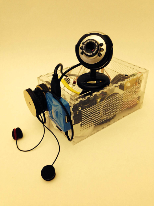
  • The box doesn’t look any particular way, and isn’t built particularly well.  The wobble box was much bigger than it needed to be to fit the parts inside it, and little to no thought went into the design and placement of the sensors.  It was sometimes difficult to know exactly when it was working or not, and some of the connections weren’t very stable.  Furthermore, the mini-USB plug on the side of the device sometimes moved around when you tried to plug in the cord.

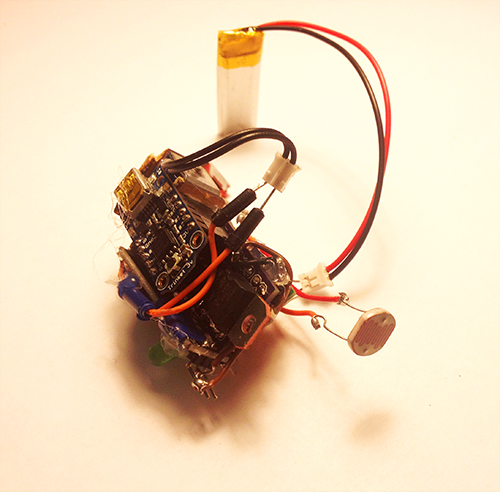
In the interested of addressing the concerns above, I completely redesigned the wobble box, abandoning the old prototype for a new model.

IMG_1636 
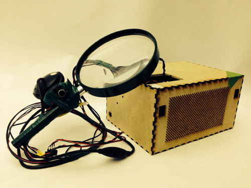
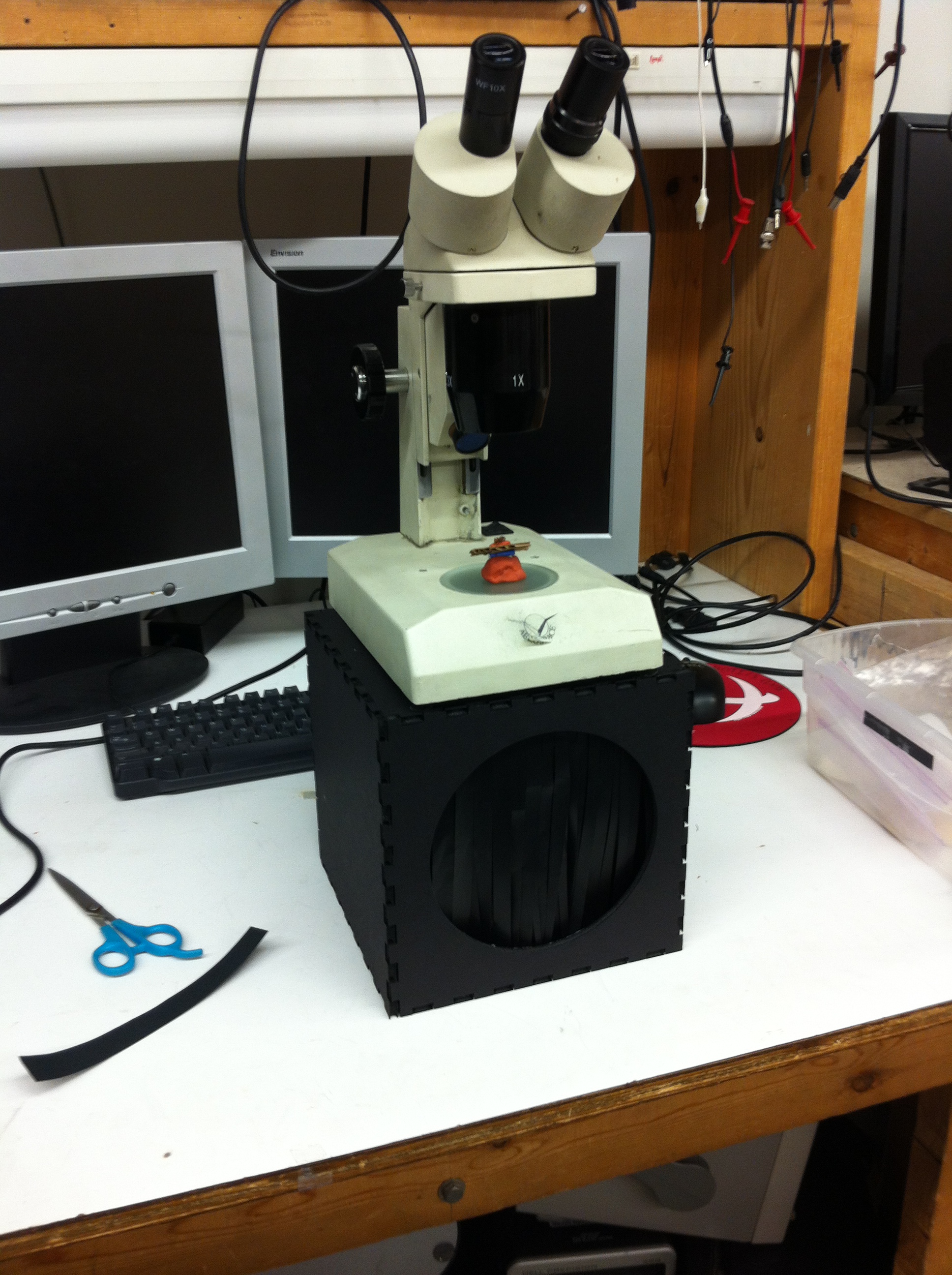
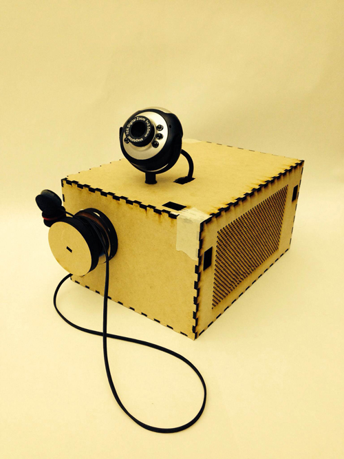
The most obviously improved element of the new box is the design.  Now that I knew exactly what the necessary electronic parts were, I removed all the extra space in the box.  The new design conserves about three square inches of space, and the holes cut for the distance sensors are much neater.

IMG_1643

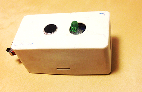
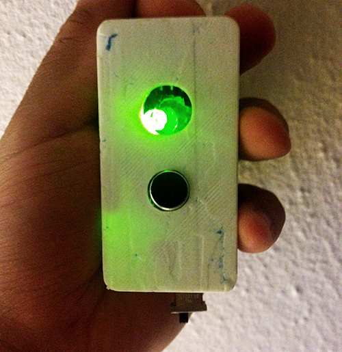
I applied three layers of surface treatment; a green primer, a metallic overcoat, and a clear glaze.  The result is a luminescent coloring, and a rubber-esque texture that prevents the box from sliding around when placed on a wooden surface.  In my opinion, it looks nice.

IMG_1639IMG_1645

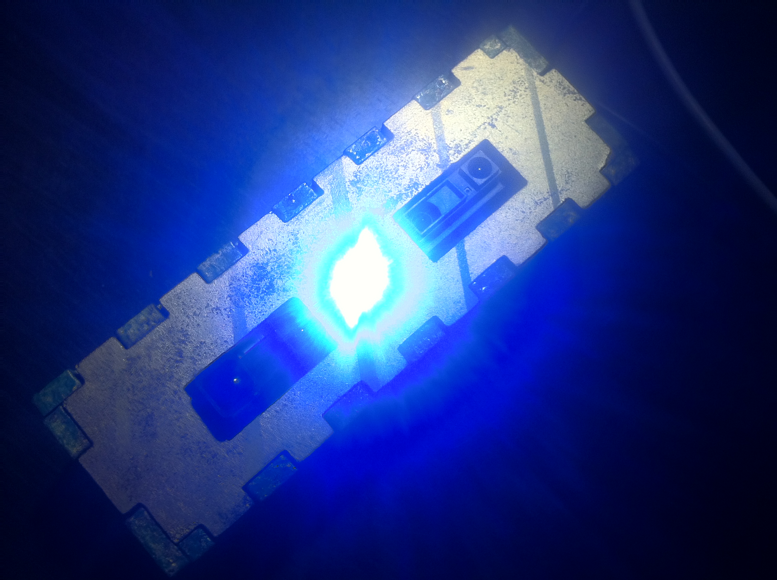
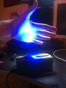
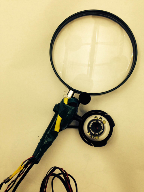
A strong LED light was placed exactly in between the two distance sensors, illuminating the ideal place for the user to put his/her hand.  This also provides a clue for the audience, making it more clear exactly what the functionality of the box is by illuminating the hand of the user.  The effect can be rather eery in dark rooms.  Perhaps most importantly, it indicates that the Teensy micro-controller has been recognized by Max, a feature lacking in the last prototype.  This saved me many headaches the second time around.

IMG_1640

IMG_1644

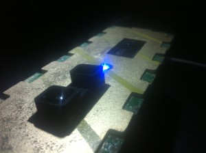
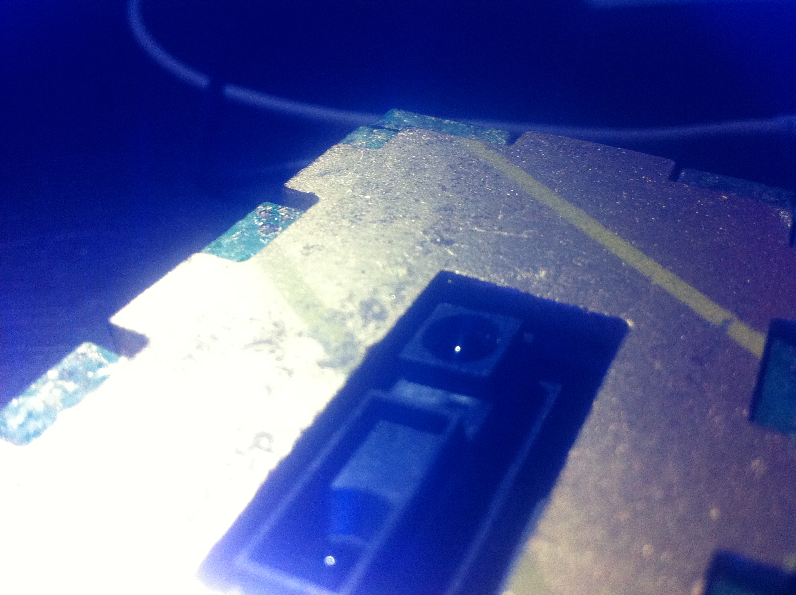
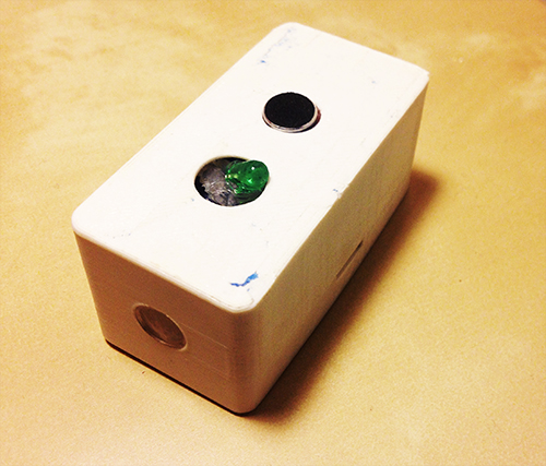
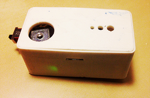
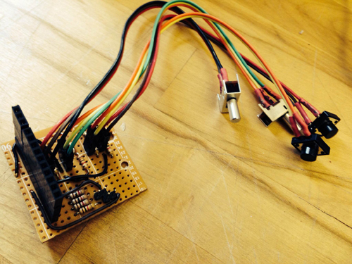
The new box has two new distance sensors, with differing ranges.  One transmits very fine values between about 2 inches and 10 inches, the other larger values between about 4 and 18 inches.  Staggering the ranges like this allows for a whole new world of control for the user, such as tilting the hand from front to back, using two hands with complete independence, etc.

IMG_1642

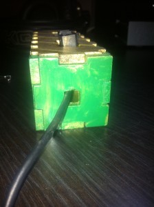
Finally, I moved the entire USB connection to the interior of the device, electing to instead just create a hole for the cord to come out.  After then securing the Teensy within the box, the connection was much stronger than it was in the previous prototype.

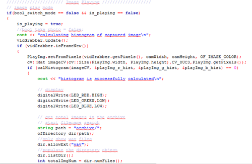
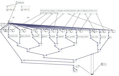
In addition to fixing the hardware, I created a few new software environments between Max and Ableton that allow for more expressive use of the box.  The first environment utilized both Max and Ableton Live to create an interactive art piece.  As the user stimulated the two distance sensors, a video captured by the laptop camera would be distorted along with an audio track of the user talking into the computer microphone.  Moving forward, my goals were to extend the ability to use the box as a true instrument, by granting a way to trigger pitches using only the box and a computer.  To achieve this, I wrote a max for live patch that corresponds a note sequence-stepper with a microphone.  Every time the volume of the signal picked up by the microphone exceeds a certain threshold, the melody goes forward by one step.  Using this, the user can simply snap or clap to progress the melody, while using the box to control the timbre of the sound.  I then randomized the melody so that it selected random notes from specific scales, as to allow for improvisation.  The final software environment I wrote, shown below, allows for the user to trigger notes using a midi keyboard, and affect the sounds in a variety of ways using the box.  For the sake of exhibiting how this method can be combined with any hardware the user desires, I create a few sounds on an APC40 that I then manipulate with the box.

Final Project “ImSound”: Ding

Audio,Final Project,OpenCV — Ding Xu @ 9:31 pm

ImSound: Record/Find your sounds in images

We run into a lot of sounds in our lives and sometimes we will naturally come up with certain color with those sounds. We may even form a memory of our city or living environment with some interesting sounds and colors. As for me, when I listen to some fast and happy tempo I could sense a color of dark red and when I run into some soft music, I may feel it is green or blue. Different people may have different feeling about different sounds. Therefore, ImSound is a devices aiming to encourage people collecting useless sounds in lives, all kinds of noise for example, convert them to certain colors based on their understanding and play the similar mixed sounds when run into a new image. The process stems from sound to image and then to sound.

For the user himself/herself, this device may help him/her convert some useless or even annoying sounds into some interesting funny sounds and  find new information from it. As for others, this devices is like a business card of a user’s specific understanding about the world’s sounds and share to others.

Hardware improvement:

Based on last time’s feedback, people failed to get aware of the focus when capturing an image. Thus, in the final prototype, I use a magnifier attaching a camera and a mic as a portable capture device for people to focus where the sound and where they will capture an image, with a metaphor of finding sounds in our lives. Instead of several buttons to control the recording and taking image, a single push button in the handle of magnifier is used to trigger taking a photo and then automatically record a 3s sound.

Final1

Final3

Final2

Software improvement:

Instead of using the whole histogram of images, I converted the image from RGB to HSV and used the H value for histograms with 12 bins (variable). That is to say, the images will be divided into 12 clusters based on their major color. Each image is classified and the sound will be recorded into corresponding track contributing to the library of that color. That is to say, every color has a soundtrack which belong to this cluster. Then a granular analysis is used to divided the sound into small grains and remix them for a new sound of that class. When changing to the play mode, the H histogram is computed and the corresponding sound will be played.

I used a OF ofxMaxim with FFT processing for granular analysis, but the output sound effect is not that good. The speed of sound is changed but without much similar grains connecting together. This is a main aspect I should improve for the next step of this project.

 Demo Video:

Future Plan:

1. the most important is to get more in-depth granular analysis to re-mix the sounds. My current thought is to combine the grains with their similarities among each other. The funny part is that with the growing of number of recording sounds, the output sound is dynamic changing and form some new sound.

2. Take some more actual image and sound to test the effects of whole process. Aiming to a specific type of sound may be a good choice, such as city noise.

Conclusion/Acknowledge:

Although this project is far from fully completion, I learned a lot in this process, not only the technologies such as RPI, openFrameworks and Linux; more importantly, I learned a lot about input/output design, mapping, and telling story (a point I did not do well). It teaches me to think why should we design this device and inspired me to think whom and where does a device will be used in my future projects. Thanks Ali Momeni very much for his suggestions and all the conversations during this whole process of project, and all the reviewers and classmates who help me to improve my ideas and project.


Audible Color by Momo Miyazaki, CIID

Audio,OpenCV,Reference — Ding Xu @ 9:06 pm

audible color from Momo Miyazaki on Vimeo.

Final Project “TAPO”: Liang

TAPO: Speak Rhythms Everywhere

Idea Evolution:

This project comes from the original idea that people can make rhythms through the resonant property and material of cups and interacting with cups. However, as the project progresses, it is more interesting and proper for people to input the rhythms by speaking than do gestures on cups. It also extends the context from cups to any surface because of the fact that each object has resonant property and specific material. So, the final design and function of TAPO have a significant change from the very raw idea. The new story here is:

“Physical objects have resonance property and specific material. Tap object gives different sound feedback and percussion experience. People are used to making rhythms by beating objects. So, why not provide a tangible way not only allowing people to make rhythms with physical objects around she/he, but also enriching the experience by some computational methods. The ultimate goal for this project is that ordinary people can make and play rhythms with everyday objects, even perform a piece of percussion performance.”

Design & Key Features:

TAPO is an autonomous device that generates rhythms according to people’s input (speech, tapping, making noise). TAPO can be placed on different surfaces, like desk, paper, ground, wall, window… With different material and the object’s resonant property, it is able to create different quality of sound. People’s input gives the pattern of rhythm.

System diagram

a) voice, noise, oral rhythm, beat, kick, knock, oral expression… can be the user input

b) using photo resistor to trigger recording

c) get rid of accelerometer, add led to indicate the state of recording and rhythm play

Hardware

It is composed of several hardware components: a solenoid, a microphone electret, a transistor, a step-up voltage regulator, a Trinket board, a colourful LED, a photocell, a switch and a battery.

photo1


photo2


Fabrication

I used 3D printing enclosure to package all parts together. The holes with different sizes on the bottom are used for different usage, people can mount a hook or a suction. With these extra tools, it can be places on any surfaces. The other big hole is used for solenoid to beat the surface. The two holes on the top  side are used to show microphone and LED light separately. On each side, there is a hole for photo resistor and switch.

photo3 photo4

TAPO finally looks like this:

photo6 photo5 photo7 photo8 photo9

Demostration:

Final introduction video:

Conclusion & Future Work:

This project gives me a lot more than technology. I learn about how to design and develop a thing from a very raw idea, and keeping thinking about its value, target users, and possible scenarios in a quick and iterative process. I really enjoy the critique session, even though it is tough and sometimes makes me feel disappointed. The positive suggestions are always right and lead me to a high level and more correct direction. I realise my problems on motivation, design, and stroytelling from these communications. Fortunately, it gets much more reasonable from design thinking to value demonstration. I feel better when I find something more valuable and reasonable comes up in my mind. It also teaches me the significance of demonstrating my work when it is hard to describe and explain. In the public show on Dec. 6th, I found people would like to play with TAPO and try different inputs, they are curious about what kind of rhythm TAPO could generate. In the following weeks, I will refine the hardware design and rich the output (some control and digital outputs).

Acknowledge:

I would like to thank very much Ali Momeni for his advices and support on technology and idea development, and all the guest reviewers who gave me many constructive suggestions.

Final Project Presentation – Ziyun Peng

Assignment,Final Project,Max,Sensors — ziyunpeng @ 10:20 pm

Face Yoga Game

Idea

There’s something interesting about the unattractiveness that one goes through on the path of pursuing beauty. You put on the facial mask to moisturize and tone up your skin while it makes you look like a ghost. You do face yoga exercises in order to get rid of some certain lines on your face but at the mean time you’ll have to many awkward faces which you definitely wouldn’t want others to see. The Face Yoga Game aims at amplifying the funniness and the paradox of beauty by making a game using one’s face.

Set-up

Myoelectric sensors -> Arduino —Maxuino—> Max/MSP (gesture recognition)—OSC—> Processing (game)

Myoelectric sensor electrodes are replaced with electric fabrics so to be sewed onto a mask that the player is going wear. The face gestures that correspond to the face yoga video are pre-learnt in Max/MSP using the Gesture Follower external developed in IRCAM. When the player is making facial expressions under the mask, it will be detected in Max/MSP, the corresponding gesture number will be sent to Processing to determine if the player is performing the right gesture.

How does the game work?

Face_Yoga


The game is in the scenario of “daily beauty care” where you have a mirror, a moisturizer and a screen for game play.

Step 1: Look at the mirror and put on the mask

Step 2: Apply the moisturizer (for conductivity)

Step 3: Start practicing with the game!

The mechanism is simple, the player is supposed to do the same gesture as the instructor does in order to move the object displayed on the screen to the target place.

The final presentation is in a semi-performative  form to tell

Final Project Presentation — Haochuan Liu

Assignment,Audio,Final Project,OpenCV — haochuan @ 10:09 pm

Drawable Stompbox

Write down your one of your favorite guitar effects on a piece of paper, then play your guitar, you will get the sound what you’ve written down.

Here is the final diagram of this drawable stompbox:

Screenshot 2013-11-27 22.11.45


After you write down the effects on a piece of paper, the webcam which is above the paper will capture what you’ve written into a software written in openframeworks. The software will analysis the words and do the recognition using optical character recognition (OCR). When your write the right words, the software will tell puredata to turn on the specific effect through OSC, you will finally hear what you’ve written when you play your guitar.

The source code of this software can be found here.

Here is a demo of how this drawable stompbox works.

Feedback from my final presentation:

I have got a lot of good idea and advice for my drawable stompbox as below:

1. Currently writing down a word to get the effects has no relationship with ‘drawing’. It is more like a effect selection using word recognition.

2. I was thinking of drawing simple face on the paper instead of just boring words. How about using a webcam directly to scan real people’s face, getting their emotion on their face and then find the relationship between different faces and different effects.

3. Words recognition is so hard, for there are a lot of factors to make it doesn’t work well, such as the hand-writing, the resolution of the webcam and the light of environment.

Following work:

For the following weeks, I decide to make my instrument a real drawable stompbox. I will begin with a very simple modulation:

People can simply draw the ‘wave’ like this:

2013-11-27 23.03.24 2013-11-27 23.03.34 2013-11-27 23.03.43

From this drawing, it is easy to define and map the amplitude and the frequency.

2013-11-27 23.03.43 2013-11-27 23.03.34 2013-11-27 23.03.24


Then I will use the ‘wave’ from the drawing to do a modulation with the original guitar signal. People can draw different type of waves to try how the sound changes.


Final Presentation – Spencer Barton

The Black Box

Put your hand into the black box. Inside you will find something to feel. Now take a look through the microscope. What do you feel? What do you see?

The Box and Microscope

2013-11-19 20.00.16

Inside the Box

2013-11-19 19.43.03

Under the Microscope

2013-11-17 00.03.12

When we interact with small objects we cannot feel them. I can hold the spider but I cannot feel it. The goal here is to enable you to feel the spider, to hold it in your hand. Our normal interaction with small things is in 2D. We see through photographs or a lens. Now I can experience the spider though touch and feel its detail. I have not created caricatures of spiders, I copied a real one. There is loss of detail but the overall form is recreated and speaks to the complexity of living organisms at a scale that is hard to appreciate.

The box enables the exploration of the spider model before the unveiling of the real spider under the microscope. The box can sense the presence of a hand and after a short delay, enabling the viewer to get a good feel of the model, a light is turned on to reveal the spider under the microscope.

Explanation of the Set-up

The Evolution of Ideas

As I created the models I found that my original goal of recreation was falling short. Instead of perfect representations of the creatures under the microscope, I had white plastic models that looked fairly abstract. The 123D models were much more realistic representations because of their color. My original presentation ideas focused around this loss of detail and the limits of the technology. However, what I came to realize was were the strengths of the technology lay: the recreation of the basic form of the object at a larger scale. For example someone could hold the spider model and get a sense of abdomen versus leg size. Rather then let someone view the model I decided to only let them feel the model.

Feedback and Moving Forward

The general feedback that I got was to explore the experience of the black box in more depth. There were two key faults with the current set-up. First the exposure of the bug under the microscope happened too soon. Time is needed for the viewer to form a questions of what is inside the black box. Only after that question is created should the answer be shown under the microscope. The experience in the box could also be augmented. The groping hand inside the box could also be exposed to other touch sensations, it could activate sound or trigger further actions. The goal would be to lead the experience toward the unveiling. For example sounds of scuttling could be triggered for the spider model.

The second piece of feedback lay with the models themselves. First it was tough to tell that the model in the box was an exact replica of the bug under the microscope. The capture process losses detail and the model creation through 3D printing adds new textures. The plastic 3D models in particular were not as interesting to touch as the experience was akin to playing with a plastic toy.

To recognize and rectify these concerns this project can be improved in a few directions. First I will improve the box with audio and a longer exposure time. Rather then look through the microscope I will have a laptop that displays the actual images that were used to make the model. The user’s view on this model with then be controlled by how they have rotated the model inside the box.

I will try another microscope and different background colors to experiment with the capture process and hopefully improve accuracy. I will redo the model slightly larger with the CNC. MDF promises to be a less distracting material to touch. Additionally the fuzziness of MDF is closer to the texture of a hairy spider.

Final Project Milestone 3 – Ding Xu

Audio,Final Project,Machine Vision,OpenCV — Ding Xu @ 10:24 pm

1. GPIO control board soldering

In order to use GPIO of RPI for digital signal control, I built a control protoboard  with two switches and two push buttons connecting a pull-up/pull-down registers respectively. A female header was used to connect the GPIO of RPI to get the digital signal.

In RPI, I used the library WiringPi for GPIO signal reading. After compiling this library and include the header files, three easy steps are used to read the data from digital pins: (1). wiringPiSetup() (2). set up pinmode: PinMode(GPIOX,INPUT) and (3). digitalRead(GPIOX) or digitalWrite(GPIOX)

photo_7(1)


2. software design

In openframeworks, I used  the library Sndfile for recording and ofSoundPlayer for sound output. There are two modes: capture and play. Users are expected to record as many as sounds in their lives and take an image each time recording a sound. Then in the play mode, the camera will capture a surrounding image and the sound tracks of similar images will be played.  The software workflow is as follows:

Capture:

Play:

code

3. system combination

Connecting the sound input/output device, RPI, singal control board and camera, the system is as follows:

photo_31

photo30

Final Project Milestone 3 – Ziyun Peng

Assignment,Final Project,Max,Software — ziyunpeng @ 10:05 pm

Since my project has switched from a musical instrument to a beauty practice instrument that’s used to play the face yoga game that I’m going to design, hence my 3rd milestone then is to make the visuals and the game mechanics.

First is to prepare the video contents. What I did was to split the videos into 5 parts according to the beauty steps. After watching each clip, the player is supposed to follow the lady’s instruction and hold the gesture for 5 seconds – being translated in the language of the game is to move the object on the screen to the target place by holding the according gesture.

The game is made in processing, and it’s getting gesture results from the sensors in the wearable mask in Max/MSP via OSC protocol.

max_patch


Examples are shown as followed:

game_step_1


game_step_2

video credits to the wonderful face yoga master Fumiko Takatsu.


Final Project Milestone 3 – Haochuan Liu

Assignment,Final Project,OpenCV,Software — haochuan @ 9:51 pm

In my milestone 3, I’ve reorganized and optimized  all the parts of my previous milestone including optical character recognition in openframeworks, communication using OSC between openframeworks and puredata, and all of the puredata effect patches for guitar.

Here is the screenshot of my drawable interface right now:

Screenshot 2013-11-25 22.14.49

Here is the reorganized patch in puredata:

Screenshot 2013-11-25 22.17.13


Also, I’ve applied the Levenshtein distance algorithm to improve the accuracy of the optical character recognition. For a number of tests made with this algorithm, the recognition accuracy can reach about 93%.

I am still thinking of what can I do with my drawable stompbox. For the begining, I was thinking this instrument could be a good way for people to play guitar and explore the variety of different kind of effects. I believed that using just a pen to write down the effects you want might be more interesting and interactive instead of using real stombox, or even virtual stompbox in computer. But now, I have realized that there is no way for people to use this instrument instead of a very simple controller such as a foot pedal. Also, currently just writing the words to get the effects is definitely not a drawable stompbox.


Next Page »
This work is licensed under a Creative Commons Attribution-Noncommercial-Share Alike 3.0 Unported License.
(c) 2024 Hybrid Instrument Building 2014 | powered by WordPress with Barecity