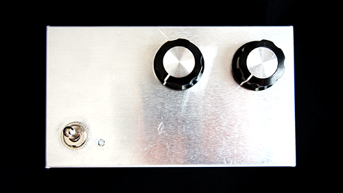
Final Project Documentation: The Wobble Box 2.0

Arduino,Assignment,Audio,Final Project,Instrument,Max,Sensors,Software — Tags: — Jake Berntsen @ 9:46 pm

Presenting my original “wobble box” to the class and Ali’s guests was a valuable experience.  The criticisms I received were relatively consistent, and I have summarized them to the best of my ability below:

  • The box cannot be used to create music as an independent object.  When I performed for the class at the critique, I was using an Akai APC40 alongside the wobble box.  I was using the APC to launch musical ideas that would then be altered using the wobble box, which I had synced to a variety of audio effects.  The complaint here was that it was unclear exactly how much I was doing to create what the audience was hearing in real time, and very clear that I wasn’t controlling 100% of the noises coming out of my computer.  At any rate, it was impossible to trigger midi notes using the wobble box, which meant the melody had to come from an external source.
  • The box only has one axis to play with.  At the time of the critique, the wobble box only had one working distance sensor attached to the Teensy, which meant I could only control one parameter at a time with my hand.  Many spectators commented that it seemed logical to have at least two, allowing me to get more sounds out of various hand motions, or even using two hands at once.
  • The box doesn’t look any particular way, and isn’t built particularly well.  The wobble box was much bigger than it needed to be to fit the parts inside it, and little to no thought went into the design and placement of the sensors.  It was sometimes difficult to know exactly when it was working or not, and some of the connections weren’t very stable.  Furthermore, the mini-USB plug on the side of the device sometimes moved around when you tried to plug in the cord.

In the interested of addressing the concerns above, I completely redesigned the wobble box, abandoning the old prototype for a new model.
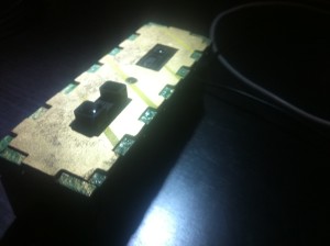
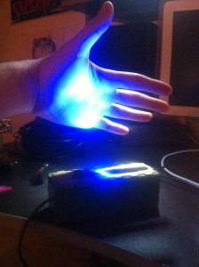
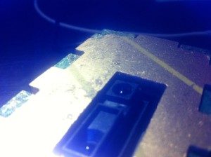
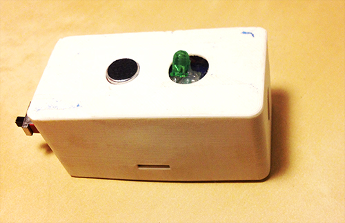
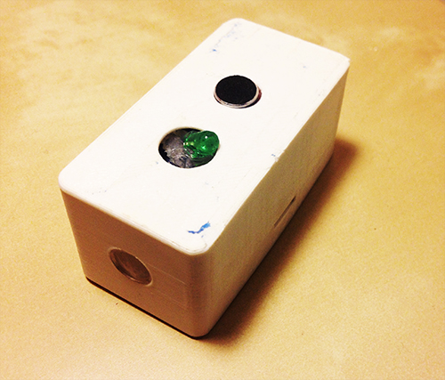
IMG_1636 The most obviously improved element of the new box is the design.  Now that I knew exactly what the necessary electronic parts were, I removed all the extra space in the box.  The new design conserves about three square inches of space, and the holes cut for the distance sensors are much neater.

IMG_1643

I applied three layers of surface treatment; a green primer, a metallic overcoat, and a clear glaze.  The result is a luminescent coloring, and a rubber-esque texture that prevents the box from sliding around when placed on a wooden surface.  In my opinion, it looks nice.

IMG_1639IMG_1645

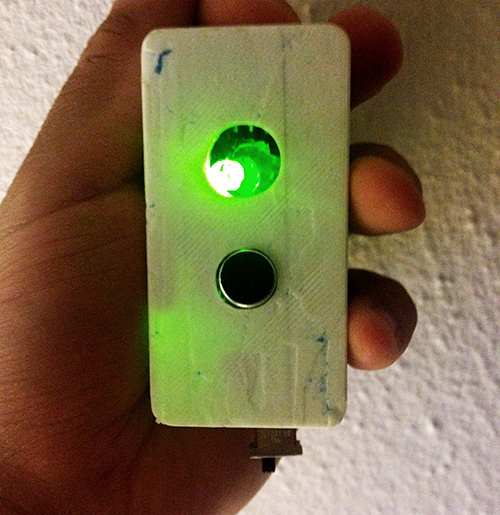
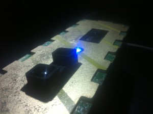
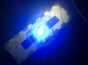
A strong LED light was placed exactly in between the two distance sensors, illuminating the ideal place for the user to put his/her hand.  This also provides a clue for the audience, making it more clear exactly what the functionality of the box is by illuminating the hand of the user.  The effect can be rather eery in dark rooms.  Perhaps most importantly, it indicates that the Teensy micro-controller has been recognized by Max, a feature lacking in the last prototype.  This saved me many headaches the second time around.
IMG_1640

IMG_1644

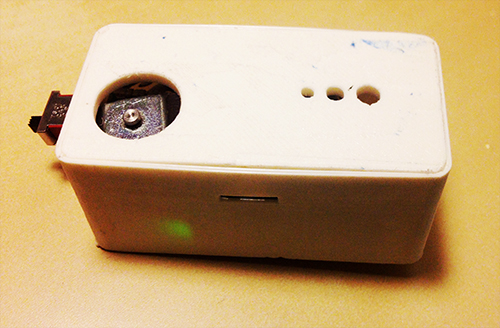
The new box has two new distance sensors, with differing ranges.  One transmits very fine values between about 2 inches and 10 inches, the other larger values between about 4 and 18 inches.  Staggering the ranges like this allows for a whole new world of control for the user, such as tilting the hand from front to back, using two hands with complete independence, etc.
IMG_1642

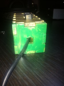
Finally, I moved the entire USB connection to the interior of the device, electing to instead just create a hole for the cord to come out.  After then securing the Teensy within the box, the connection was much stronger than it was in the previous prototype.

In addition to fixing the hardware, I created a few new software environments between Max and Ableton that allow for more expressive use of the box.  The first environment utilized both Max and Ableton Live to create an interactive art piece.  As the user stimulated the two distance sensors, a video captured by the laptop camera would be distorted along with an audio track of the user talking into the computer microphone.  Moving forward, my goals were to extend the ability to use the box as a true instrument, by granting a way to trigger pitches using only the box and a computer.  To achieve this, I wrote a max for live patch that corresponds a note sequence-stepper with a microphone.  Every time the volume of the signal picked up by the microphone exceeds a certain threshold, the melody goes forward by one step.  Using this, the user can simply snap or clap to progress the melody, while using the box to control the timbre of the sound.  I then randomized the melody so that it selected random notes from specific scales, as to allow for improvisation.  The final software environment I wrote, shown below, allows for the user to trigger notes using a midi keyboard, and affect the sounds in a variety of ways using the box.  For the sake of exhibiting how this method can be combined with any hardware the user desires, I create a few sounds on an APC40 that I then manipulate with the box.

Final Project “TAPO”: Liang

TAPO: Speak Rhythms Everywhere

Idea Evolution:

This project comes from the original idea that people can make rhythms through the resonant property and material of cups and interacting with cups. However, as the project progresses, it is more interesting and proper for people to input the rhythms by speaking than do gestures on cups. It also extends the context from cups to any surface because of the fact that each object has resonant property and specific material. So, the final design and function of TAPO have a significant change from the very raw idea. The new story here is:

“Physical objects have resonance property and specific material. Tap object gives different sound feedback and percussion experience. People are used to making rhythms by beating objects. So, why not provide a tangible way not only allowing people to make rhythms with physical objects around she/he, but also enriching the experience by some computational methods. The ultimate goal for this project is that ordinary people can make and play rhythms with everyday objects, even perform a piece of percussion performance.”

Design & Key Features:

TAPO is an autonomous device that generates rhythms according to people’s input (speech, tapping, making noise). TAPO can be placed on different surfaces, like desk, paper, ground, wall, window… With different material and the object’s resonant property, it is able to create different quality of sound. People’s input gives the pattern of rhythm.

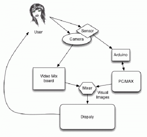
System diagram

a) voice, noise, oral rhythm, beat, kick, knock, oral expression… can be the user input

b) using photo resistor to trigger recording

c) get rid of accelerometer, add led to indicate the state of recording and rhythm play

Hardware

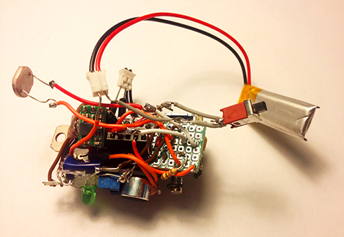
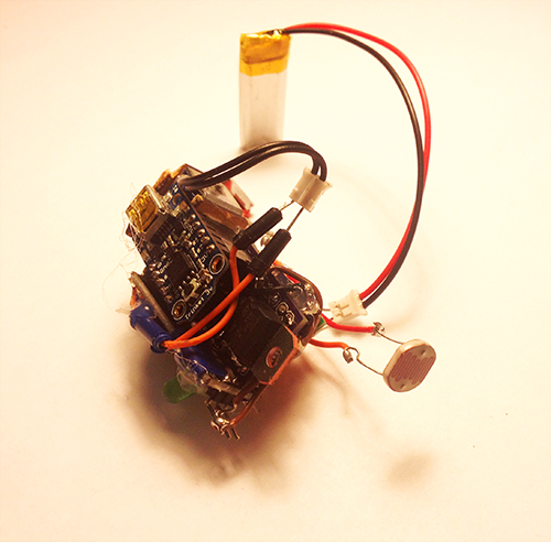
It is composed of several hardware components: a solenoid, a microphone electret, a transistor, a step-up voltage regulator, a Trinket board, a colourful LED, a photocell, a switch and a battery.

photo1


photo2


Fabrication

I used 3D printing enclosure to package all parts together. The holes with different sizes on the bottom are used for different usage, people can mount a hook or a suction. With these extra tools, it can be places on any surfaces. The other big hole is used for solenoid to beat the surface. The two holes on the top  side are used to show microphone and LED light separately. On each side, there is a hole for photo resistor and switch.

photo3 photo4

TAPO finally looks like this:

photo6 photo5 photo7 photo8 photo9

Demostration:

Final introduction video:

Conclusion & Future Work:

This project gives me a lot more than technology. I learn about how to design and develop a thing from a very raw idea, and keeping thinking about its value, target users, and possible scenarios in a quick and iterative process. I really enjoy the critique session, even though it is tough and sometimes makes me feel disappointed. The positive suggestions are always right and lead me to a high level and more correct direction. I realise my problems on motivation, design, and stroytelling from these communications. Fortunately, it gets much more reasonable from design thinking to value demonstration. I feel better when I find something more valuable and reasonable comes up in my mind. It also teaches me the significance of demonstrating my work when it is hard to describe and explain. In the public show on Dec. 6th, I found people would like to play with TAPO and try different inputs, they are curious about what kind of rhythm TAPO could generate. In the following weeks, I will refine the hardware design and rich the output (some control and digital outputs).

Acknowledge:

I would like to thank very much Ali Momeni for his advices and support on technology and idea development, and all the guest reviewers who gave me many constructive suggestions.

Final Project Presentation–Wanfang Diao

Arduino,Assignment,Final Project — Wanfang Diao @ 5:04 pm


More demos:

Note cubes from Wanfang Diao on Vimeo.

Note Cubes from Wanfang Diao on Vimeo.

Final Project Proposal – Liang He

Final Project Proposal – Wanfang Diao

Group Project: Wireless Data + Wireless Video System (part 2)

Arduino,Assignment,Hardware,Max,OpenCV,Submission — jmarsico @ 11:07 pm

Overview

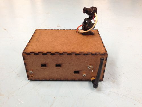
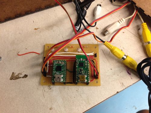
This project combines a Wixel wireless data system, servos, microcontrollers and wireless analog video in a small, custom-built box to provide wireless video with  remote viewfinding control.

IMG_0052-2


Hardware

Camera-Box:

  • Wixel wireless module
  • Teensey 2.0 (code found HERE)
  • Wireless video transmitter
  • 3.3v servo (2x)
  • FatShark analog video camera
  • 12v NiMH battery
  • 9v battery
  • 3.7v LiPo battery
  • Adafruit LiPo USB charger

IMG_0048


Control Side:

  • Alpha wireless video receiver
  • Analog to Digital video converter (ImagingSource DFG firewire module)
  • Wixel Wireless unit
  • Max/MSP (patch found HERE)


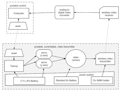
System Diagram:

wireless_servo_camera-2


Tips and Gotchas:

1. Max/MSP Patch Setup:

  1. Connect the your preferred video ADC to your computer
  2. Open the patch
  3. hit the “getvdevlist” message box , select your ADC in the drop-down menu
  4. hit the “getinputlist” message box, select the correct input option (if there are multiple on your unit)
  5. if you see ““NO SIGNALS” in the max patch:
  • double check the cables… this is a  problem with older analog video
  • verify that the camera and wireless transmitter are powered at the correct voltage

2. Power Choices:

  1. We ended up using three power sources within the box. This isn’t ideal, but we found that power requirement for the major components (teensey, wixel, transmitter, camera) are somewhat particular.  Also keep in mind that the video transmitter is the largest power consumer at  around 300mA.
 

 Applications:


1. Face Detection and 2. Blob Tracking


Using the cv.jit suite of objects, we built a patch that pulls in the wireless video feed from the box and uses openCV’s face detection capabilities to identify people’s faces. The same patch also uses openCV’s background removal and blob tracking functions to follow blob movement in the video feed.

Future projects can use this capability to send movement data to the camera servos once a face was detected, either to center the person’s face in the frame, or to look away as if it were shy.

We can also use the blob tracking data to adjust playback speed or signal processing parameters for the delayed video installation mentioned in the first part of this project.


3. Handheld Control

IMG_0065-2


In an effort to increase the mobility and potential covertness of the project, we also developed a handheld control device that could fit in a user’s pocket. The device uses the same Wixel technology as the computer-based controls, but is battery operated and contains its own microcontroller.

Group Project: Multi-Channel analog video recording system (part 2)

Arduino,Assignment,Submission — mauricio.contreras @ 2:17 pm

Overview

Eight video cameras present eight different views into a dynamic world. They can be oriented a number of ways including inward or outward on a subject.

Our basic setup is a box with the eight cameras arranged along the top. Cables run from the cameras to the base of the box where they are connected to power sources and a video multiplexer. The base also contains an Arduino which is used to control the mux. Power for the mux is supplied via the Arduino. A basic diagram of this setup can be seen below (this setup matches our “Fat Shark” application, as described in this post, but also can be generalized).

Hardware Details

Cameras

These cameras are generic analog mini cameras you can buy on the internet or steal from the artfab lab. They can be fed with 9-12V, and are provided with a 3 conductor cable: V+, GND and video.


Camera boxes

The camera boxes were constructed out of MDF. There is nothing special about the design except that there are holes to allow the camera to poke out as well as for the cord to come in. A good place to create a box is here: boxmaker.rahulbotics.com/.
Our camera cords are secured inside by foam padding and a zip-tie.


Open-beam structure

Open beam is very structural. openbeamusa.com/


Cords

Each camera has power input and video output. We used three 1-to-4 power splitters to distribute  power from a single 9V source to the 8 cameras and other components. The video output eventually terminates as RCA to connect to the video MUX.


Mux

The mux takes 8 analog video inputs, a selector input, an enable input, a power source, and 1 analog video output. This board is a collaboration between Ray Kampmeier and Ali Momeni, and more information can be found here www.raykampmeier.net


Arduino

The arduino controls the mux selector from either being programmed to switch channels or by an external controller eg a computer or a phone outputting OSC. Any arduino would do.


Immersion RC

The video output can be routed to a sender antenna that takes in a video input and power. Their website is: www.immersionrc.com


Fat Shark

The goggles with screens inside: www.fatshark.com


Code

All our code and documentation is located on github github.com/sbarton272/VideoMux.

Looking Outwards: Fat Shark

As shown in the diagram, the video multiplexer is connected to the immersion RC chip that sends a radio signal to the Fat Shark, where a single output video appears through the goggles. Fat Shark is a very interesting device because it allows you to see videos and images that are not necessarily where you can traditionally view. As of now, the cameras are fixed in place on the Open-beam structure. The structure is robust enough for mobility, which allows for a wide range of possibilities on the location of the system.

Looking Inwards

The setup of the cameras allows us to rotate the cameras inwards. For this application, we place an object in the middle, and use the eight cameras to view it from different angles. In order to hold the object in place, we cut out a square piece of masonite, that is placed on top of four screws and can be moved up and down depending on the size of the object. Similar to the Looking Outwards application, the videos are controlled by the phone through touchOSC.

Third Application

We took the outward facing camera set-up and did a few shoots using our new compass controller. Here are the results:

Experiment 1:


Experiment 2:


Fourth Application: An Image Capture System for 8 Cameras with Different Angles.

The aim of this project is building a image capture system with our camera box for 8 cameras. The capture system is composed by a real time processing software : Pure Data and Open source hardware platform : Arduino. Function is simple like that first, we made a connection between a video multiplexer and arduino, so we can control and choose which camera and angle we want to use. And, in Pure data patch for this combination (Arduino  and Video multiplexer), we can use a user interface which help to choose which camera with GUI and make a captured and file-saved images into PC. And then, we can use these images for making 3D scan image and multi viewed photo like a panorama image.

test


Group members

  • Mauricio Contreras
  • Spencer Barton
  • Patra Virasathienpornkul
  • Sean Lee
  • JaeWook Lee
  • David Lu

Group Project: Multi-Channel analog video recording system (part 1)

Arduino,Assignment,Submission — mauricio.contreras @ 5:31 pm

The project is centered around an 8-to-1 analog video multiplexer board. This board is a collaboration between Ray Kampmeier and Ali Momeni, and more information can be found here.

In the present setup, 8 analog small video cameras (“surveillance” type) are connected as inputs to the board, and the output is connected to a monitor. The selection of which of the 8 inputs gets routed to the output is done by an Arduino, which in turn maps the input of a distance sensor to a value between 1 and 8. Thus, one can cycle through the cameras simply by placing an object at a certain distance of the sensor. The connection diagram can be seen below:

A picture of the board with 8 inputs is displayed below (note the RCA connectors):

Video Multiplexer board

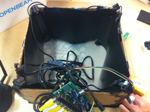
The original setup built for showcasing the project uses a box shaped cardboard structure to hold a camera in each of its corners, with the cameras pointing at the center of the box (see below).

Initial setup for 8 cameras

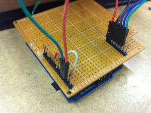
A simple “shield” board was designed to facilitate the interface between the Arduino, the distance sensor and the video mux.

Arduino shield

Improvements

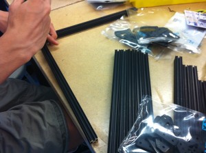
The current camera frame is of cardboard which is not the most robust of materials. A new frame will be constructed of aluminum bars assembled in a strong cube:2013-09-21 22.17.04 

This is the cube being assembled:

2013-09-20 15.22.04

Wires attachments for the cameras will be routed away from the box to a board for further processing.

Project Ideas

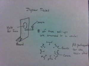
1) Jigsaw faces

Our faces hold a universal language. We propose combining the faces of eight people to create a universal face. Eight cameras are set-up with one per person. The participants place their face through a hole in a board so that the camera only sees the face. These set-ups are arranged in a circle so that all the participants can see each other. The eight faces are taped and a section of face is selected from each person to combine into one jigsaw face. This jigsaw face is projected so that the participants can see it. This completes the feedback loop. The jigsaw face updates in real time so as the participants share an experience their individual expressions combine in the jigsaw face.

The Jigsaw Face  will consist of a few boards (of wood) for people to put their face through. Each board will have a camera attachment and all the cameras will be attached to a central processor. The boards will be arranged so that people face each other across a circle. This will enable feedback among the participants.

2013-09-21 22.17.18

2) The well of time : Time traveling instrument

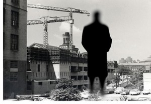
I’m still thinking about the meaning of 8 cameras and why we need and what we can do originally. And, I assume that 8 cameras mean 8 different views and also it could be 8 different time points distinguishably. After arriving this point, I realized we can suggest a moment and situation that is a mixed timezone and image with a user’s present image from each camera and the old photo from in the past which is triggered by a motion or distance sensor, attached with each camera.

Here is a sample image of my thought. This image contains the moment of now and the past time when the computer science building had constructed.

sean1_500

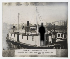
And, if a user stand with another camera, we could represent the image like below. The moment of first introducing the propeller steam boat. basically, this is the artistic way of time traveling. So, our limitation by black and white camera couldn’t be problem and in this case, it could be benefit.

sean2-500

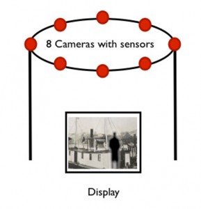
For this idea, of course, we have to make some situation and installation looks like this.

sean3_500


More precisely, it has this kind of structure.
sean4-500
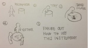
As a result, an example interaction scenarios with a user and diagram.
sean5-500
sean6_500

3) Object interventions

Face and body expressions can tell a lot about people and their feelings towards the surroundings or the objects of interaction. Imagine attaching eight cameras to a handheld object or a large sculpture. With eight cameras as the inputs, the one output will be the video from the camera that is activated by a person interacting with it in that specific area. The object can range from a small handheld object like a rubik’s cube, to a large sculpture at a playground. We think it will be very interesting to see the changes in face and body expressions as a person gets more (or less) comfortable with the object. It might be more interesting to hide these cameras so that the user will be less conscious of their expressions because they do not realize they are being filmed. It will be more difficult to do that with a large public sculpture, but we can do a prototype of a handheld object where we can design specific places where the cameras should locate so that they cannot be seen.

4) Body attachment

When we see the world we see it from our eyes. Why not view the world from our feet. Perceptions can change with a simple change in vantage point. We propose to place cameras on key body locations: feet, elbows, knees and hands in order to view the world from a new vantage point as we interact with our surroundings. Cameras would be attached via elastic and wires routed to a backpack for processing.

Group members:

  • Mauricio Contreras
  • Spencer Barton
  • Patra Virasathienpornkul
  • Sean Lee
  • JaeWook Lee
  • David Lu

Assignment 2 “Musical Painting” by Wanfang & Meng(2013)

Arduino,Assignment,Max,Sensors,Submission — meng shi @ 1:28 am

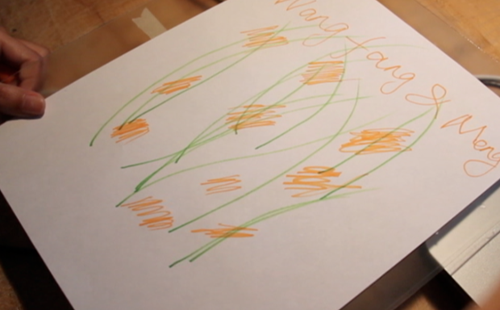
musical painting


What:

This idea came from the translation between music and painting. When somebody draws some picture, the music will change at the same time. So, it looks like you draw some music:)

How:

We use sensor to test the light, get the analog input , then transform it  to sound. I think the musical painting is a translation from visible to invisible, from seeing to listening.

Why:

It is fun to break the rule between different sense. To on the question, the differences between noise, sound and music, personally thinking, that the sound is normal listening for people. The noise may be disturb people. The music is a sound beyond people’s expect. So based on the environment, people’s idea will also change, we will create more suitable music .

Assignment 2: “Comfort Noise” by Haochuan Liu & Ziyun Peng (2013)

Arduino,Assignment,Submission — ziyunpeng @ 10:40 pm

fini_500

Idea

People who don’t usually pay attention to noise would often take it for granted as disturbing sounds, omitting  the musical part in it – the rhythm, the melody and the harmonics. We hear it and we want to translate and amplify the beauty of noise to people who didn’t notice.

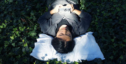
Why pillow?

The pillow is a metaphor for comfort – this is what we aim for people perceiving from hearing noise through our instrument, on the contrary to what noise has been impressed people.

When you place your head on a pillow, it’s almost like you’re in a semi-isolated space – your head is surrounded by the cotton, the visual signals are largely reduced since you’re now looking upwards and there’s not that much happening in the air. We believe by minimizing the visual content, one’s hearing would become more sensitive.

Make

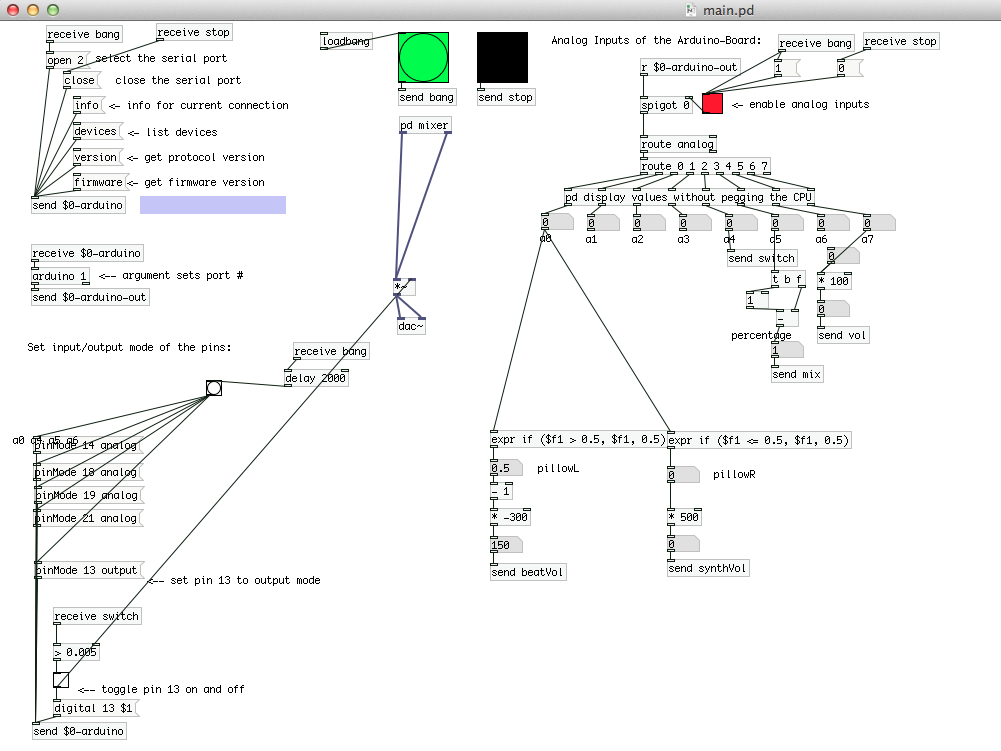
We use computational tools ( Pure Data & SPEAR) and our musical ears to extract the musical information in the noise, then map them to the musical sounds (drum and synth ) that people are familiar with.

The Pduino (for reading arduino in PD) and PonyoMixer (multi-channel mixer) helped us a lot.

pd

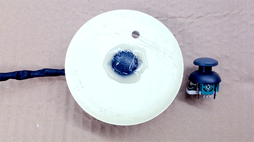
Inside the pillow, there’s a PS2 joystick  used to track user’s head motions. It’s a five-direction joystick but in this project we’re just using the left and right. We had a lot of fun making this.

sensor_500

Here’s the mix box we made for users to adjust the volume and the balance of the pure noise and the musical noise extraction sounds.

mixBox

The more detailed technical setting is as listed below:

Raspberry Pi – running Pure Data

Pure Data – reading sensor values from arduino and sending controls to sounds

Arduino Nano – connected to sensors and Raspberry Pi

Joystick – track head motion

Pots – Mix and Volume control

Switch – ON/OFF

LED – ON/OFF indicator


Next Page »
This work is licensed under a Creative Commons Attribution-Noncommercial-Share Alike 3.0 Unported License.
(c) 2024 Hybrid Instrument Building 2014 | powered by WordPress with Barecity