Final Project Milestone 3 – David Lu
Milestone 3: make the hardware
My original 3rd milestone had to do with connecting a haptic feedback controller with the simulation of robotic motion, which by this time had turned into real motion, and the device chosen as described before is a smartphone since it provides an IMU and a vibrator, all with a standard and well proven programming API.
My original intent was to use the device’s IMU to track position and orientation, each in 3 axis, providing effectively 6 degrees of freedom. My pursuit is for a very natural gestural interaction that would mimic one’s own hand orientation and position in space, to be imitated by the robot changing it’s own head position and orientation. My assumption was that standalone positioning based on integrating the accelerometer’s readings twice was a method that must have been solved by now, and I started searching for code. Yet, to my surprise, it seems this is not true and the constraints lie mainly on the double integration, the first of which leaves a constant error, and hence the second multiplies that constant with time, meaning the error grows linear with time! The drift most algorithms (at least the ones available on the web) render is even of tens of centimeters per second, which is completely unusable for the application in mind. In the case of orientation, this is completely different because there is only one integration to be made, plus there are at any given time 2 vectors of reference against which to correct: gravity and the magnetic north. To sum up, whereas one can get very accurate orientation from an IMU, linear positioning is still very much a work in progress, the underlying reasons being physical more than technological.
This immediately cut 3 degrees of freedom from my ideal application, the most important ones at that (the assumption being that one can probably use tricks to change the head’s orientation but use real degrees of freedom for it’s position, as opposed to the other way round. This is pure intuition though). I faced the decision of changing technology to visual tracking or keep using the IMU, now only with orientation. Even though kinect based motion tacking seems to be pretty plug&play these days, I had no previous experience and decided the semester was too advanced to have a setback as not being able to show anything functional in the end, whereas I was already somewhat acquainted at this time with the smartphone workflow I had developed. I decided then to stay on this path.
I devised a TCP/IP socket based client (Android smartphone) – server (robot controller) application. It uses the smartphones orientation (software sensor provided by Android based on fusing the raw information from accelerometer, gyroscopes and magnetometer/compass) in each axis to generate steps that offset the robots head position in each axis.
The motion result was pretty much just as cut as what I had obtained with hardcoded targets, which left me with a feeling of disappointment. See video below, and please notice how unnatural this piecewise movement feels.
This piecewise motion is not related to the smartphone input information, but to the way the robot is controlled. Through the trials, becoming acquainted with people who have done extensive work with the robots (Mike Jeffers, Madeline Gannon, Zack Jacobson-Weaver, Ali Momeni, Jaremy Ficca, Josh Bard, Kevyn McPhail, up to then) and online research, I came to know that at least ABB robots, being developed for industrial use, are aimed towards rigid precision. This means motion commands are based on targets and are not meant to be interrupted in the middle, which is exactly what is required for responsive gestural control (real time interrupts). The next and final milestone shows the way of how I’ve dealt with this limitation.
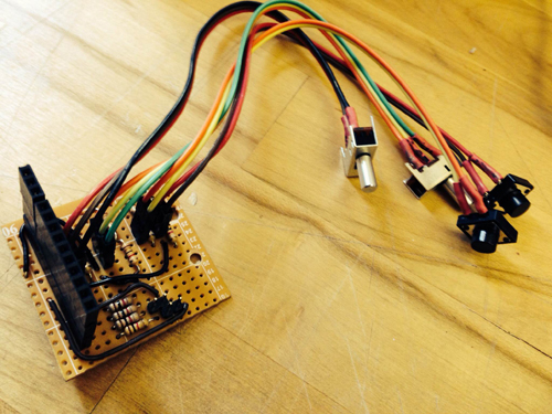
1. GPIO control board soldering
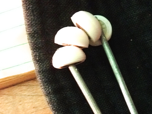
In order to use GPIO of RPI for digital signal control, I built a control protoboard with two switches and two push buttons connecting a pull-up/pull-down registers respectively. A female header was used to connect the GPIO of RPI to get the digital signal.
In RPI, I used the library WiringPi for GPIO signal reading. After compiling this library and include the header files, three easy steps are used to read the data from digital pins: (1). wiringPiSetup() (2). set up pinmode: PinMode(GPIOX,INPUT) and (3). digitalRead(GPIOX) or digitalWrite(GPIOX)
2. software design
In openframeworks, I used the library Sndfile for recording and ofSoundPlayer for sound output. There are two modes: capture and play. Users are expected to record as many as sounds in their lives and take an image each time recording a sound. Then in the play mode, the camera will capture a surrounding image and the sound tracks of similar images will be played. The software workflow is as follows:
Capture:
Play:
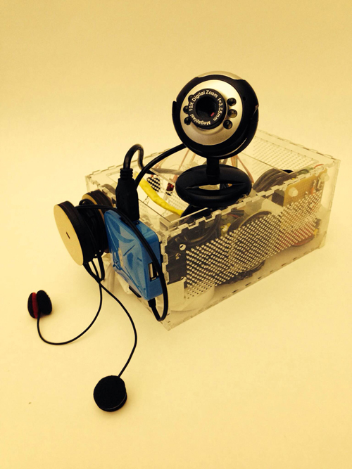
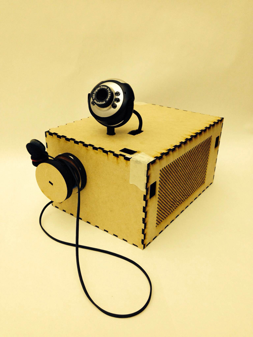
3. system combination
Connecting the sound input/output device, RPI, singal control board and camera, the system is as follows:
Since my project has switched from a musical instrument to a beauty practice instrument that’s used to play the face yoga game that I’m going to design, hence my 3rd milestone then is to make the visuals and the game mechanics.
First is to prepare the video contents. What I did was to split the videos into 5 parts according to the beauty steps. After watching each clip, the player is supposed to follow the lady’s instruction and hold the gesture for 5 seconds – being translated in the language of the game is to move the object on the screen to the target place by holding the according gesture.
The game is made in processing, and it’s getting gesture results from the sensors in the wearable mask in Max/MSP via OSC protocol.

Examples are shown as followed:


video credits to the wonderful face yoga master Fumiko Takatsu.
In my milestone 3, I’ve reorganized and optimized all the parts of my previous milestone including optical character recognition in openframeworks, communication using OSC between openframeworks and puredata, and all of the puredata effect patches for guitar.
Here is the screenshot of my drawable interface right now:

Here is the reorganized patch in puredata:
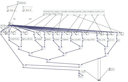
Also, I’ve applied the Levenshtein distance algorithm to improve the accuracy of the optical character recognition. For a number of tests made with this algorithm, the recognition accuracy can reach about 93%.
I am still thinking of what can I do with my drawable stompbox. For the begining, I was thinking this instrument could be a good way for people to play guitar and explore the variety of different kind of effects. I believed that using just a pen to write down the effects you want might be more interesting and interactive instead of using real stombox, or even virtual stompbox in computer. But now, I have realized that there is no way for people to use this instrument instead of a very simple controller such as a foot pedal. Also, currently just writing the words to get the effects is definitely not a drawable stompbox.
After taking time to consider exactly what I hope to accomplish with my device, the aim of of my project has somewhat shifted. Rather than attempt to build a sound-controller of some kind that includes everything I like about current models while implementing a few improvements, I’ve decided to focus only on the improvements I’d like to see. Specifically, the improvements I’ve been striving for are simplicity and interesting sensors, so I’ve been spending all of my time trying to make small devices with very specific intentions. My first success has been the creation of what I’m calling the “Wobble Box.”


Simply stated, the box contains two distance sensors which are each plugged into a Teensy 2.0. I receive data from the sensors within Max, where I scale it and “normalize” it to remove peaks, making it more friendly to sound modulation. While running Max, I can open Ableton Live and map certain audio effects to parameters in Max. Using this technique I assigned the distance from the box to the cutoff of a low-pass filter, as well as a slight frequency modulation and resonance shift. These are the core elements of the traditional Jamaican/Dubstep sound of a “wobble bass,” hence the name of the box. While I chose this particular sound, the data from the sensors can be used to control any parameters within Ableton.


Designing this box was a challenge for me because of my limited experience with hardware; soldering the distance sensors to the board was difficult to say the least, and operating a laser-cutter was a first for me. However, it forced me to learn a lot about the basics of electronics and I now feel confident in my ability to design a better prototype that is smaller, sleeker, and more compatible with similar devices. I’ve already begun working on a similar box with joysticks, and a third with light sensors. I plan to make the boxes connectible with magnets.
 For my presentation in class, I will be using my device as well as a standard Akai APC40. The wobble box is not capable or meant to produce its own melodies, but rather change effects on existing melodies. Because of this, I will be using a live-clip launching method to perform with it, making a secondary piece of hardware necessary.
Based on the feedback I got, I’ve finished the second iteration of the design, which looks sleek, more packaged, and more portable.
Friction stick problem is mostly fixed, and I’ve changed the stick – glass distance to make it fit for the sponges.
Also to solve the crazy cabling problem I’ve created an Arduino Due(! yes “Due” – not duemilanove) Shield. Which I’m expecting to arrive from fabrication this week.

The past two weeks were dedicated to building out the dynamic video sequencing software. As a primary goal of this project was to create seamless playback across many unique video clips, building a system with low-latency switching was key. Another goal of the project was to build reactive logic into the video sequencing.
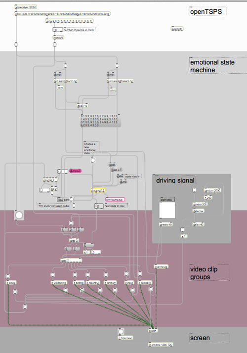
I will explain how I addressed both of these challenges later when I explain the individual components. Below is a high-level diagram of the software suite.
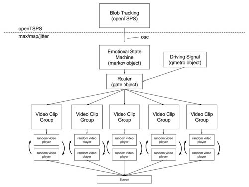
At the top of the diagram is openTSPS, an open source blob tracking tool built with openFrameworks by Rockwell Labs. openTSPS picks up webcam or kinect video, analyzes it with openCV and sends OSC packets that contain blob coordinates and other relevant events. For this project, we are only concerned with ‘personEntered’ events and knowing when the room is empty.
 openTSPS
Blow openTSPS in the above diagram is the max/msp/jitter program, which starts with a probabilistic state machine that is used to choose which group of videos will play next. The state machine relies on Nao Tokui’s markov object, which uses a markov chain to add probability weights to each possible state change. This patch loads two different state change tables: one for when people are present and one for when the room is empty. This relates to a key idea of the project: that people act very differently when they are alone or around others.
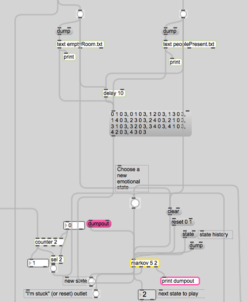 state transition with markov object
The markov state transition machine is connected to a router that passes a metro signal to the different video groups. The metro is called the ‘Driving Signal’ in the top diagram. The video playback section of the patch relies on a constantly running metro that is routed to one of seven double-buffered playback modules, which are labeled as emotional states according to the groups of video clips they contain.
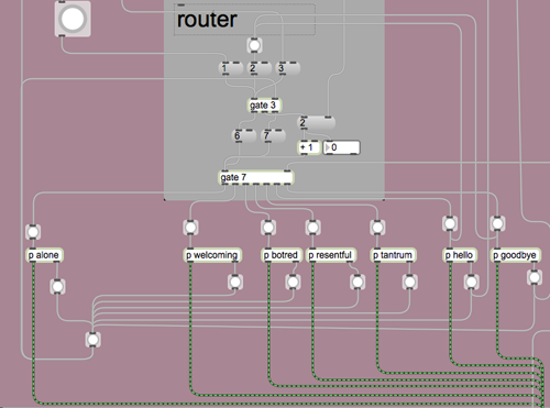 router with video group modules
Each video group module contains two playback modules. The video group module controls which of the two playback modules is running.
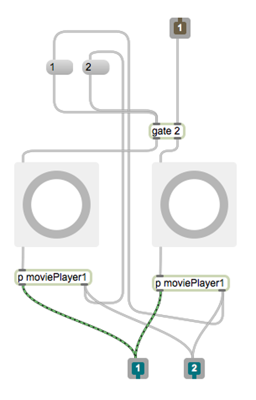 video group module
While one playback module is playing, the other one loads a new, random video from a list of videos.
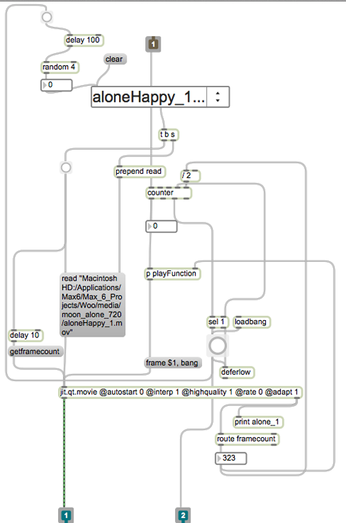 playback module
Here is a shot of the entire patch, from top to bottom:
 “woo” max/msp/jitter patch
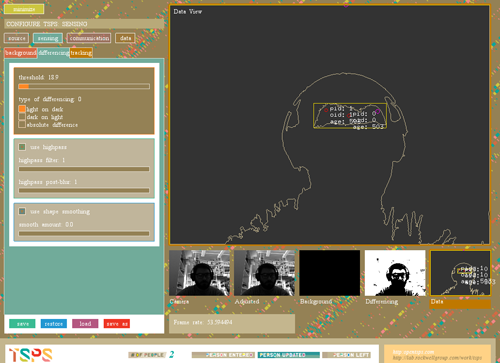
The software works well on its own. Once connected to openTSPS’s OSC stream, it starts to act up. The patch is set up to bypass the state transition machine on two occasions: when a new person enters the room and when the last person leaves the room. To do this properly, the patch needs correct data from openTSPS. In its current location, openTSPS (paired with a PS3eye) is difficult to calibrate, resulting in false events being sent the application. One option is to build a filter at the top of the patch that only allows a certain number of entrances or ’empties’ within a given time period. Another option is to find a location which has more controllable and consistent light.
Another challenge is that the footage was shot before the completion of the software. As a result, much of the footage seems incomplete and without emotion. To make the program more responsive to visitors, the clips need to be shorter (more like ~2 seconds each instead of ~9, which is the average for this batch).
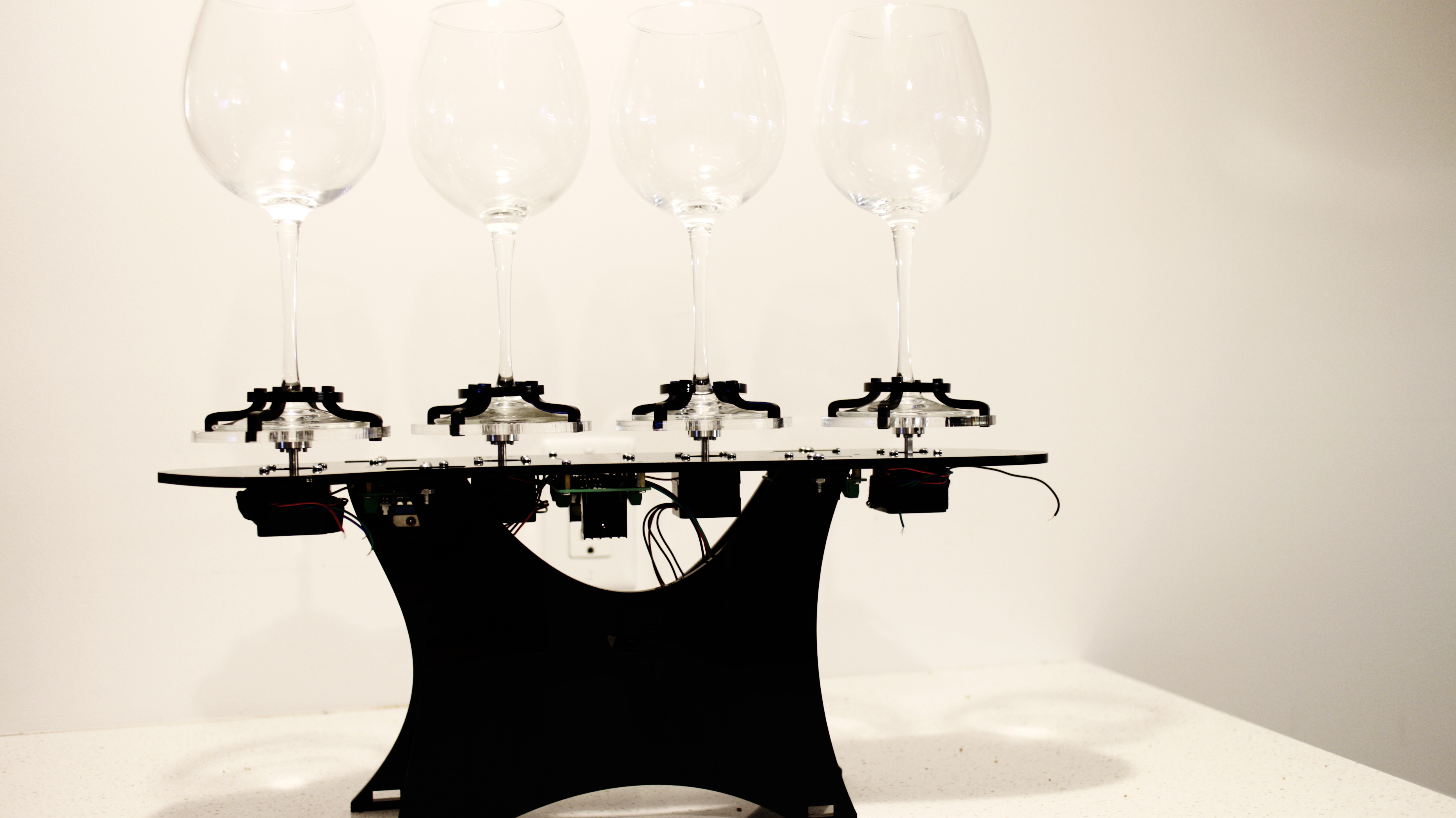
After about 12 days, OSH Park fabricated and delivered my boards. Yes, they are fantastic purple and look like exactly what I expect. I soldered and assembled every components together to test the board. Finally, all boards work with all the components but the transistor. I used smaller one instead of TIP 120. For some reason, it could work with Trinket board. So, I used TIP 120 again with my final board.

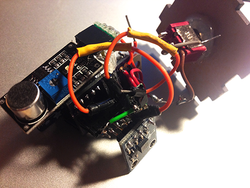
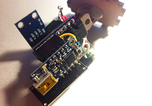
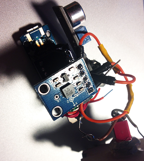
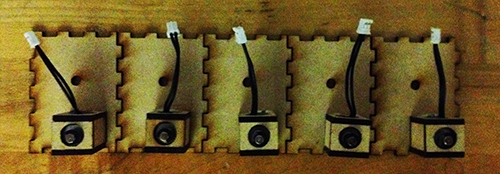
To solve the problem of gestures and how user interacts with cup and Tapo, I decided to use a microphone to record user’s input (oral rhythm, voice, and even speech). The idea is quite simple: since the electret microphone turns analog voice data into digital signal, I can just make use of the received signal and generate certain beat for a rhythm. That is more reasonable interaction for users and my gestures can be put into two categories: trigger the recording and clear the recorded rhythm. The image below shows the final look of the hardware part, including the PCB board, Trinket board, transistor, step-up voltage regulator, solenoid, accelerometer, electret microphone, and a switch.
All parts should be enclosed in a little case. At the beginning I was thinking of 3D printing a case and using magnets to fix the case on the cup. I 3D printed some buckets with magnet to see the magnetic power. It seemed not very well in attracting the whole case. The other thing looks difficult for 3D printing case was that it was not easy to put the entire hardware part in and get it out.
Then I focused on laser cutting. I created a box for each unit and drilled one hole for solenoid, one hole for microphone and a hole for hook. I experienced three versions: the first one left one hole for the wire of solenoid to go through, thereby connecting with the main board. But the solenoid could not be fixed quite well (I used strong steel wire to support it); The second version put the solenoid inside the box and opened a hole on the back facet, so that it could tap the cup it was mounted on, but the thickness of the box avoided the solenoid to touch object outside; In the final version I drilled a hole on the upper plate for the switch, and modified the construction for solenoid.
Version 1

Version 2
Solenoids
Version 3
Another thing is the hook. I started with a thick and strong steel wire and resulted in that it could not be bended easily. Then I used a thinner and softer one, so that it could be bended to any shape as the user wished.
Before program the final unit, I programmed and tested every part individually. The accelerometer and the gestures worked very well, the solenoid worked correctly, and I could record user’s voice by microphone and transferred it to certain pattern of beats. Then the challenge is how to make a right logic for all the things work together. After several days’ programming, testing, debugging, I meshed up all logics together. The first problem I met was the configuration of Trinket, which led to my code could not be burned to the board. Then the sequence of different module messed up. Since the micro controller processed data and events in a serial sequence, so the gesture data could not be “timely” obtained while the beats of solenoid depended on several delays.
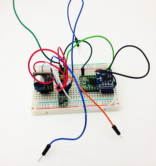
I built a similar circuit, in which my custom PCB was replaced by a breadboard, to test my code. In the test, I hoped to check if my parameters for the interval of every piece of rhythm was proper, if the data number of the gesture set was enough to recognise gestures, if specific operation causes specific events, and most importantly, if the result looked good and reasonable.
Here is the test unit:
Here is a short video demo of the test:
Milestone 2: make my computer understand the sensors
It was working but then I tore everything apart and forgot to take documentation, oops. BRB putting everything back together.
Before sending the contact mic signal into the computer, it needed to be amplified. ArtFab had some piezo preamps lying around but they required 48v phantom power and I didn’t want to deal with that so I made my own preamp.