‘SketchSynth’ by Billy Keyes

Audio,Instrument,Reference — haochuan @ 12:45 am

SketchSynth: A Drawable OSC Control Surface

SketchSynth lets anyone create their own control panels with just a marker and a piece of paper. Once drawn, the controller sends Open Sound Control (OSC) messages to anything that can receive them; in this case, a simple synthesizer running in Pure Data. It’s a fun toy that also demonstrates the possibilities of adding digital interaction to sketched or otherwise non-digital interfaces.

Final Project Proposal: Haochuan Liu

Final Project Proposal: JaeWook Lee

Assignment,Instrument,Reference,Submission — jwleeart @ 10:35 pm

Interesting Project with Ferro Liquid

Instrument,Reference — lianghe @ 8:32 pm

Wine PEG Application

Instrument,Reference — lianghe @ 7:45 pm


Other projects about glass harmonica: link

Audio Graffiti and Music in Motion: Location Based + Spatial Sound

Some impressive spatial audio examples/works by Zack Settle and company.  See Zack’s page for more…

Group Project: Multi-Channel Sound System (part 2)

Uncategorized — rkotcher @ 11:51 pm

8

Introduction:
The multi-channel sound system group is implementing a spatial instrument that allows us to interactively experience sound in space. The system includes software that controls a set of eight (currently) speakers that are positioned in space. We have two hardware setups for our project: the first is an umbrella that the speakers are mounted on, in which the listener sits beneath. The second is a wooden disk that is suspended from the ceiling. This setup allows the user to spin freely between the speakers.


Our three experiences are listed below:


Suspended Motion II


We have improved on the existing Suspended Motion project by incorporating our eight channel setup. Images from this new setup can be seen below. We are also still in the process of finding a chair that optimizes the experience. Many of the chairs we have tried are noisy or do not spin as freely as we would like. A complete description of the Suspended Motion setup and experience can be found here: teach.alimomeni.net/2013fall2/?p=2559.
67


Localization Sensitivity Experiment

This experiment involves using the eight speaker setup to test our hearing sensitivity. We start with slow impulses rotating around the circle, and these impulses gradually accelerate until it’s difficult to distinguish which direction the sound is coming from at any given instance.
32


Sonic Sculptures


In Sonic Sculptures, the user is immersed in a sound environment that they quickly discover they can manipulate with their gestures. They learn to interact with the environment to make a new composition, or they can sit and listen to their environment objectively. We’re currently using iPhone gyroscope, accelerometer, and compass data, and are also looking into using kinect data.
1


Implementing a STABLE and ROBUST system for practical use:

In both of our setups, we have tried to make our system robust enough to take out on the road! We’ve made acrylic enclosures for all the speakers, as well as designed an acrylic amplifier box which houses an amplifier array along with a charging circuit and a Li-ion battery. The battery powered amp-box gives us the mobility we’d like to make use of later. All wiring and circuits have been shifted from the breadboard to stripboard/veroboard and everything has been kept modular to allow quick assemble/dis-assembly. For the disk setup, all hardware is mounted onto a flat wooden surface as shown in the pictures above. Finally, shielded speaker wires were used to avoid any cross-talk.


Group Members:
M Haris Usmani (Persistent Member)
Robert Kotcher
Haochuan Liu
Liang He
Meng Shi
Wanfang Diao
Jake Berntsen

Group Project: Wireless Data + Wireless Video System (part 2)

Arduino,Assignment,Hardware,Max,OpenCV,Submission — jmarsico @ 11:07 pm

Overview

This project combines a Wixel wireless data system, servos, microcontrollers and wireless analog video in a small, custom-built box to provide wireless video with  remote viewfinding control.

IMG_0052-2


Hardware

Camera-Box:

  • Wixel wireless module
  • Teensey 2.0 (code found HERE)
  • Wireless video transmitter
  • 3.3v servo (2x)
  • FatShark analog video camera
  • 12v NiMH battery
  • 9v battery
  • 3.7v LiPo battery
  • Adafruit LiPo USB charger

IMG_0048


Control Side:

  • Alpha wireless video receiver
  • Analog to Digital video converter (ImagingSource DFG firewire module)
  • Wixel Wireless unit
  • Max/MSP (patch found HERE)


System Diagram:

wireless_servo_camera-2


Tips and Gotchas:

1. Max/MSP Patch Setup:

  1. Connect the your preferred video ADC to your computer
  2. Open the patch
  3. hit the “getvdevlist” message box , select your ADC in the drop-down menu
  4. hit the “getinputlist” message box, select the correct input option (if there are multiple on your unit)
  5. if you see ““NO SIGNALS” in the max patch:
  • double check the cables… this is a  problem with older analog video
  • verify that the camera and wireless transmitter are powered at the correct voltage

2. Power Choices:

  1. We ended up using three power sources within the box. This isn’t ideal, but we found that power requirement for the major components (teensey, wixel, transmitter, camera) are somewhat particular.  Also keep in mind that the video transmitter is the largest power consumer at  around 300mA.


 Applications:


1. Face Detection and 2. Blob Tracking


Using the cv.jit suite of objects, we built a patch that pulls in the wireless video feed from the box and uses openCV’s face detection capabilities to identify people’s faces. The same patch also uses openCV’s background removal and blob tracking functions to follow blob movement in the video feed.

Future projects can use this capability to send movement data to the camera servos once a face was detected, either to center the person’s face in the frame, or to look away as if it were shy.

We can also use the blob tracking data to adjust playback speed or signal processing parameters for the delayed video installation mentioned in the first part of this project.


3. Handheld Control

IMG_0065-2


In an effort to increase the mobility and potential covertness of the project, we also developed a handheld control device that could fit in a user’s pocket. The device uses the same Wixel technology as the computer-based controls, but is battery operated and contains its own microcontroller.

Group Project: OSC “Ground Control” (part 2)

Assignment,Max,Software,Submission — Can Ozbay @ 10:16 pm

Ground Control ?

I’ve been tasked to design a central control panel for all the instruments that are being built during the course. Naturally, I wanted to be platform and software-license independent, and I picked PureData as a base platform, for everyone to be able to install and use it on their computers. So it can be compiled into an app, and can be deployed rapidly on any computer in minutes and it’s as reliable as the Wi-Fi connection of the computer.

Every project utilizes OSC somehow, however even with a standardized protocol like OSC, in order to control all projects from one central control panel, all projects needed a common ground. This is where Ground Control comes in.

Screen Shot 2013-09-30 at 8.35.26 PM

Essentially it is a collection of PD patches I’ve created, but they can work harmoniously together.

8 Channel Faders / Switches

Screen Shot 2013-09-30 at 8.33.57 PM


Assuming some projects would have both variable inputs and on/off switches, I made this patch to control  8 faders, and 8 switches. Although it’s infinitely expandable, current photo shows only 8 objects.

Randomness

Screen Shot 2013-09-30 at 8.34.05 PMConsidering many people are working on an instrument, and these instruments are extraordinary hybrid instruments, I thought the control mechanism could benefit from having some level of randomness in it. This patch can generate random numbers every X seconds, in a selected number range, and send this data do the instrument. An example usage would be to control odd electrical devices in a random order.


Sequencer

Screen Shot 2013-09-30 at 8.34.28 PM

Making hybrid instruments is no fun, if computers are not being extra-helpful. I thought a step sequencer could dramatically improve some hybrid instruments by adding a time management mechanism. Using this cameras can be turned on and off for selective periods, specific speakers can be notated/coordinated or devices can be turned on/off in an orchestrated fashion.


Group Project: Multi-Channel analog video recording system (part 2)

Arduino,Assignment,Submission — mauricio.contreras @ 2:17 pm

Overview

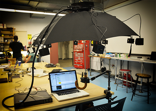
Eight video cameras present eight different views into a dynamic world. They can be oriented a number of ways including inward or outward on a subject.

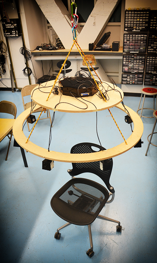
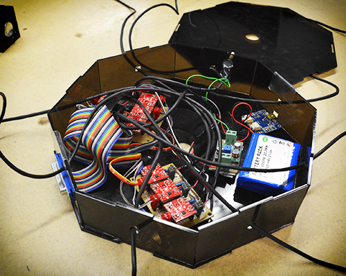
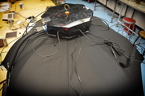
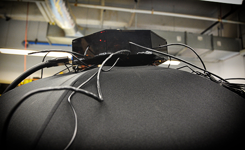
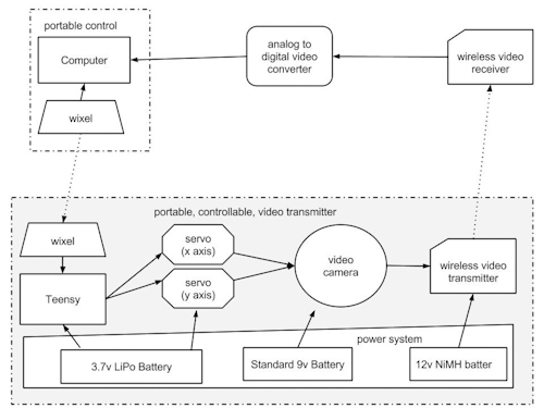
Our basic setup is a box with the eight cameras arranged along the top. Cables run from the cameras to the base of the box where they are connected to power sources and a video multiplexer. The base also contains an Arduino which is used to control the mux. Power for the mux is supplied via the Arduino. A basic diagram of this setup can be seen below (this setup matches our “Fat Shark” application, as described in this post, but also can be generalized).

Hardware Details

Cameras

These cameras are generic analog mini cameras you can buy on the internet or steal from the artfab lab. They can be fed with 9-12V, and are provided with a 3 conductor cable: V+, GND and video.
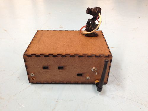
 

Camera boxes

The camera boxes were constructed out of MDF. There is nothing special about the design except that there are holes to allow the camera to poke out as well as for the cord to come in. A good place to create a box is here: boxmaker.rahulbotics.com/.
Our camera cords are secured inside by foam padding and a zip-tie.


Open-beam structure

Open beam is very structural. openbeamusa.com/


Cords

Each camera has power input and video output. We used three 1-to-4 power splitters to distribute  power from a single 9V source to the 8 cameras and other components. The video output eventually terminates as RCA to connect to the video MUX.
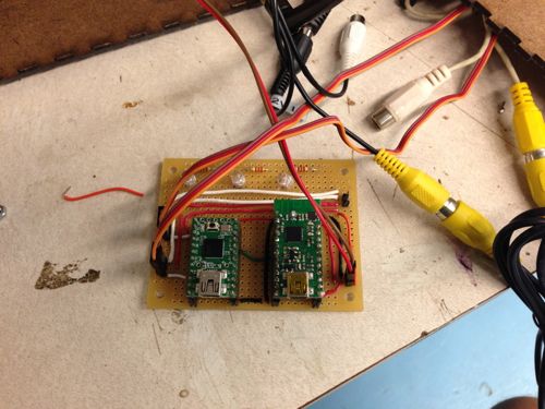
 

Mux

The mux takes 8 analog video inputs, a selector input, an enable input, a power source, and 1 analog video output. This board is a collaboration between Ray Kampmeier and Ali Momeni, and more information can be found here www.raykampmeier.net


Arduino

The arduino controls the mux selector from either being programmed to switch channels or by an external controller eg a computer or a phone outputting OSC. Any arduino would do.


Immersion RC

The video output can be routed to a sender antenna that takes in a video input and power. Their website is: www.immersionrc.com


Fat Shark

The goggles with screens inside: www.fatshark.com


Code

All our code and documentation is located on github github.com/sbarton272/VideoMux.

Looking Outwards: Fat Shark

As shown in the diagram, the video multiplexer is connected to the immersion RC chip that sends a radio signal to the Fat Shark, where a single output video appears through the goggles. Fat Shark is a very interesting device because it allows you to see videos and images that are not necessarily where you can traditionally view. As of now, the cameras are fixed in place on the Open-beam structure. The structure is robust enough for mobility, which allows for a wide range of possibilities on the location of the system.

Looking Inwards

The setup of the cameras allows us to rotate the cameras inwards. For this application, we place an object in the middle, and use the eight cameras to view it from different angles. In order to hold the object in place, we cut out a square piece of masonite, that is placed on top of four screws and can be moved up and down depending on the size of the object. Similar to the Looking Outwards application, the videos are controlled by the phone through touchOSC.

Third Application

We took the outward facing camera set-up and did a few shoots using our new compass controller. Here are the results:

Experiment 1:


Experiment 2:


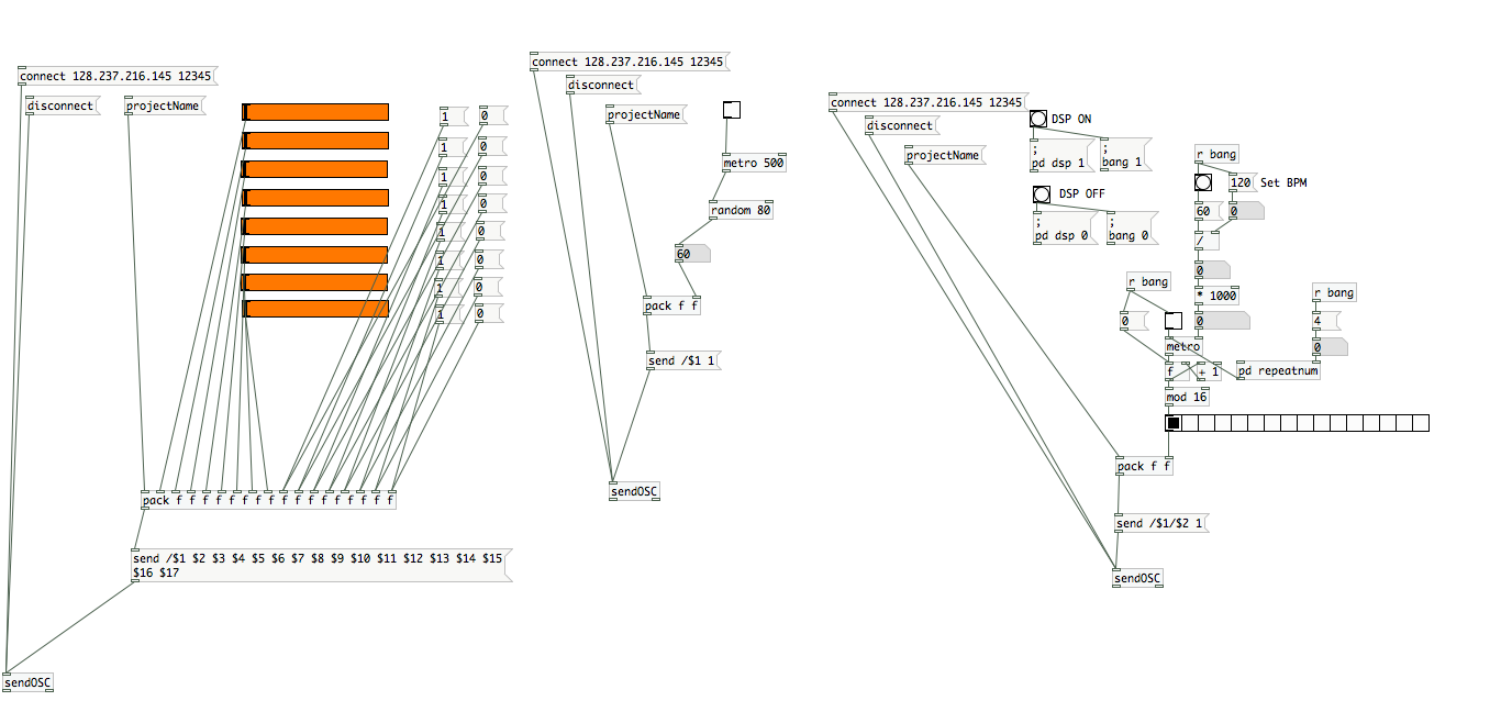
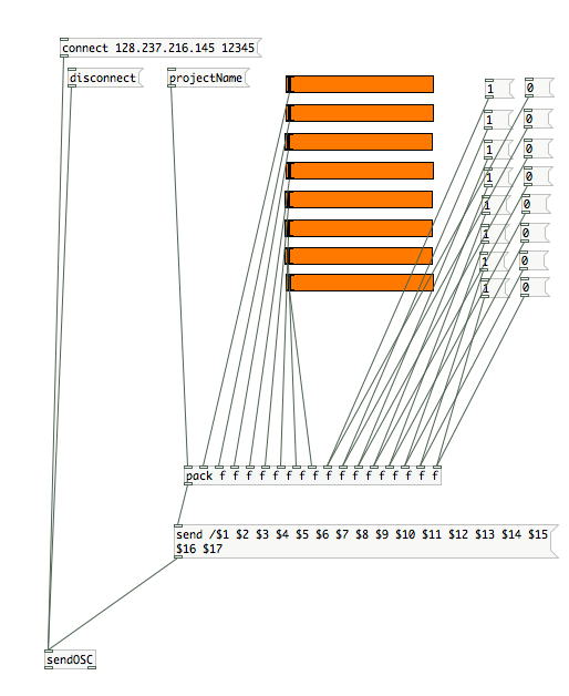
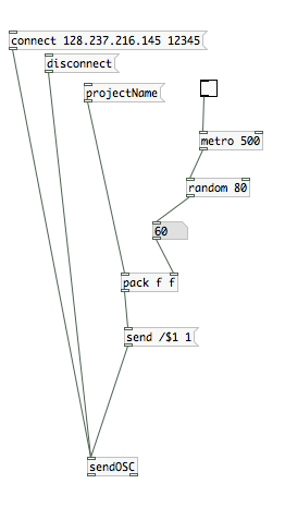
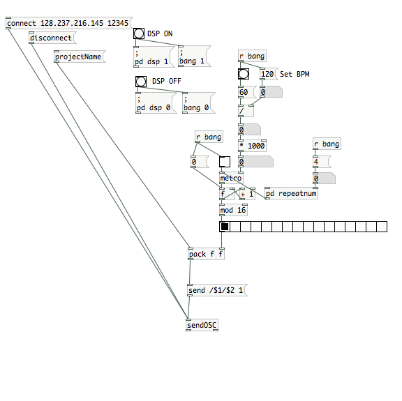
Fourth Application: An Image Capture System for 8 Cameras with Different Angles.

The aim of this project is building a image capture system with our camera box for 8 cameras. The capture system is composed by a real time processing software : Pure Data and Open source hardware platform : Arduino. Function is simple like that first, we made a connection between a video multiplexer and arduino, so we can control and choose which camera and angle we want to use. And, in Pure data patch for this combination (Arduino  and Video multiplexer), we can use a user interface which help to choose which camera with GUI and make a captured and file-saved images into PC. And then, we can use these images for making 3D scan image and multi viewed photo like a panorama image.

test


Group members

  • Mauricio Contreras
  • Spencer Barton
  • Patra Virasathienpornkul
  • Sean Lee
  • JaeWook Lee
  • David Lu
« Previous PageNext Page »
This work is licensed under a Creative Commons Attribution-Noncommercial-Share Alike 3.0 Unported License.
(c) 2025 Hybrid Instrument Building 2014 | powered by WordPress with Barecity