Final Project Milestone 1 – Robert Kotcher, M. Haris Usmani

Assignment,Final Project — Usmani @ 10:06 am

Robert and I set forth to complete the following tasks in this first week:

  • Experiment with different actuators
  • Explore the sounds we can make
  • Explore how rooms may sound differently
  • Get recordings and play with some DSP to get an understanding of things

We pretty much got through most of that, but the phase of exploration is a never ending one- we now have the prototypes we need to play around and explore sounds in different rooms, like we did this week for our class-room.

Exploring Actuators:
We considered three actuators to start with:
i) Loud speakers 2) Audio Transducers

The loud speaker and the audio transducer were to be fed by an audio signal convoluted with the class-room’s impulse response (IR). This would (in theory) make a room’s reverb twice as effective and would result in the ‘interesting’ resonant effects we need. First, this required the room’s IR to be found- we found HISSTools to be very helpful. We were able to get example patches that used HISSTools to capture IR of a room.

Spatianator - 1_1

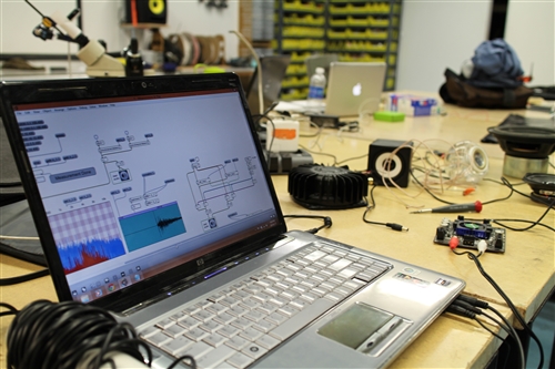
Exponentials were sweeped across the frequency range and the response recorded and processed. Once we had the IR, we simple convolved it with our audio signal and played it back to the room using speakers we had: Studio Monitors in this case.

Spatianator - 1_2

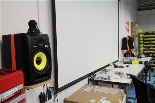
We observed that the low-frequency resonance gets very strong and it seems to trace and amplify the right frequencies to literally “shake the room”.


To explore what the high-end resonance would sound like, we used an open mid-range speaker (with a weak bass response as it had no enclosure).

Spatianator - 1_3

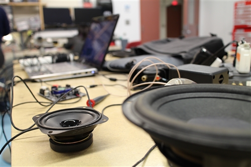
It seemed to produce more of a high ringing noise but less drastic effects than that of the low frequency resonance.

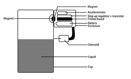
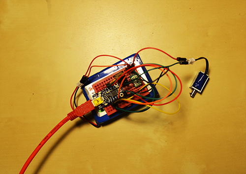
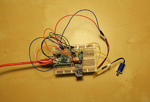
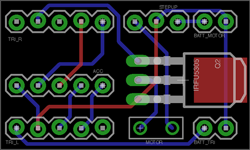
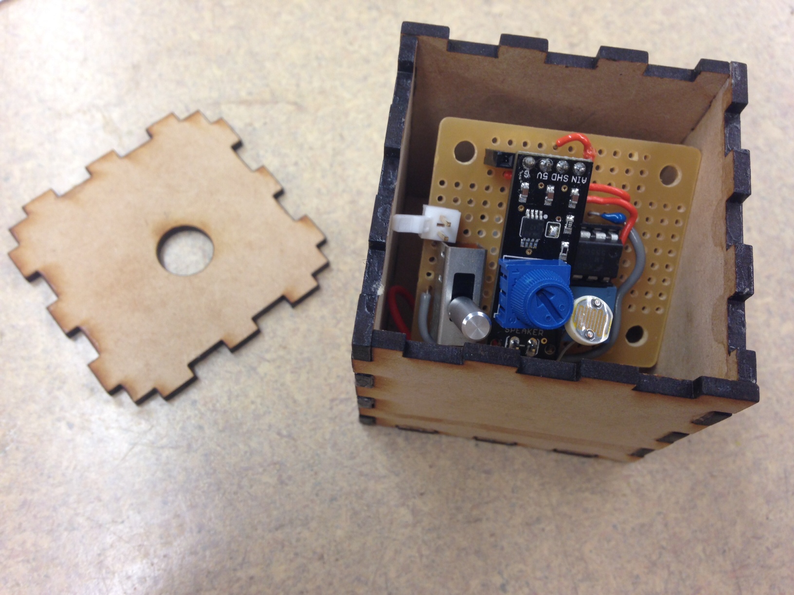
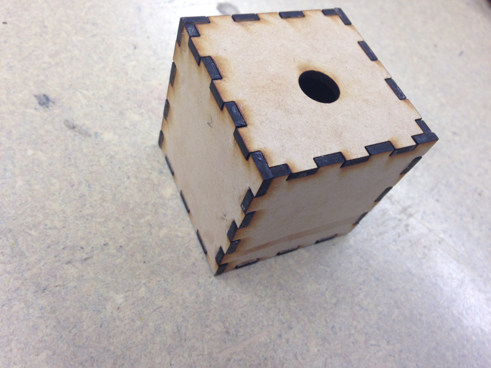
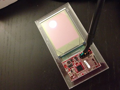
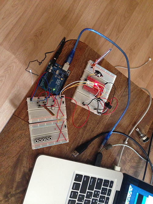
3) Electromagnetic Striker:

Spatianator - 1_4

The prototype Striker actuator was built using a Teensy, rotary solenoid and drumstick with a nylon head. We experimented with a variety of striking objects, but found that this drumstick was light and was able to characterize the room nicely, without the drumstick itself sounding too loudly.

Spatianator 1_5

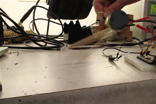
An issue we’re facing now is the solenoid making sounds of its own. We may be able to modify it or use a different type of solenoid. A final prototype will consist of a self-contained and portable actuator in an enclosed case, with a more refined attachment for the drum stick. While the software hasn’t been written yet, it will instruct the solenoid to play the room in response to the performer.

Learning Outcomes:

We plan to use the IR Response to assign characteristic sounds to our actuators- this mapping has yet to be tried and tested but we expect to get something interesting.

Also, we feel we need another actuator as the loud speaker or audio transducer are very similar as far as low frequency resonance is concerned. The transducer requires contact with the surface, so we may just choose the loud-speaker over it. A third actuator may be a scratcher.

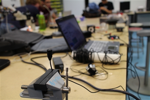
To capture the true IR of the room, we may use a pair of balanced omni-directional microphones placed at the listener’s position in the room- right now, our cost-effective condenser mic isn’t giving us the true IR but is accurate enough to get things started.

Spatianator 1_6

Throughout the course of exploration, we also kept the bigger picture in mind- these are a few changes we made to the initial setup for a more cost-effective and convenient implementation:
– Raspberry Pi replaced with Udoo (Due to the Cost of Audio I/O and Wireless Access we require)
– Having a central PC that listens to the performer and ‘conducts’ the room (sends audio/controls to crickets)

These considerations will be given more though and design decisions will be made based on more experimentation.

Final Project Milestone 1 – Spencer Barton

Final Project,Scanning — spencer barton @ 8:00 am

The Project

Our world is defined by what we see. However beneath our feet exist an enormous and elaborate system of creations. With the aid of a microscope and camera I am seeking to recreate through 3D modeling the millimeter scale for the centimeter scale that we live in. This project is enabled by key advancements in 3D modeling software such at Autodesk’s 123D Catch.

The process for capture is fairly simple. A series of photographs are taken of an object from every direction. These photographs are stitched together and distance is interpolated resulting in a 3D model. The chair model below is a good illustration. About 40 photographs were taken from a variety of angles and then uploaded to 123D Catch.

Chair Test

Milestone 1

The goal of my first milestone was to create a functioning 3D scanning jig as well as perform some research into objects to capture.

Scanning Jig

The scanning jig is based around a microscope. I began with a usb microscope, but it quickly proved not to have the necessary image resolution.

Example of the USB microscope:

t4

The Original Microscope Jig

I discovered that my iPhone camera was high enough resolution with the added advantage of being easy to work with. I got hold of a microscope from the robotics club and set-up a few tests holding my camera to the lenses. I created a rotating stand for the object with a LEGO piece, tape and cardboard.

2013-10-23 20.52.32

Lessons Learned

From this first prototype I learned that it important to have a textured surface for the rotating base. The 3D capture software relies on picking out key points in each photo, so a textured base provides more unique points for the software. I also discovered the importance of a stable camera. The model below turned out poorly as camera jitter made depth interpolation difficult.

Piece of Solder

Upgraded Jig

The first jig was upgraded first with the use of magic arms for camera stabilization as well a a sturdier turning base. The base utilized the same LEGO piece but was planted in clay in order to make the assembly flexible. I wanted to be able to change platform height and angle easily.

The Photo Platform

2013-10-28 19.48.20

Jig Results: Acorn

What to Capture?

5 ideas on interesting things to capture. I will pursue one or more.

Food

Food doesn’t always look as nice close up. This project would provide a new perspective on good food at a new scale.

Chewed Gum

2013-10-28 20.26.19


A walk in the woods

I grew up playing in the woods. It was always an adventure – new bugs lay under every rock and dirt could be molded into innumerable forts. I have gradually left the woods behind (as I imagine most of us are doing these days). My goal with this track would be to take a simple walk through the woods (Schenley Park) and record any and all interesting discoveries that I make. These critters, rocks and leaves would then be created as physical models to capture some of that excitement of discovery.

A Rolly-polly Bug

2013-10-28 17.29.52


Surfaces

We have a good sense of how a surface might feel, but how does touch translate to the physical look of a material? Surfaces would be recreated in larger scale so that roughness becomes visibly rough and the finer details of materials like velcro can be seen.

Velcro

2013-10-28 20.18.29

Close-up

Inspiration for this track comes from hyper-realism. The goal here is to take a close-up look at less elegant human features. Following the lead from Ron Mueck, these captures would transformed into larger then life models.

A Fingernail

2013-10-28 19.09.35

Fluids

Water forms differently on different surfaces. This track would explore the interaction between water on various surfaces and under varying conditions (heat, vibration, pressure, sunlight). As a comparison other fluids such as oil could be used. 3D modeling is particularly interesting as the liquids would be forming distinct forms in 3 dimensions and not just in profile. 3D printing would be a viable option as the form matters more then material in this case.

Water on a Leaf

2013-10-28 17.25.13

Final Project Milestone #1: Liang

Assignment,Final Project,Hardware,Sensors — lianghe @ 5:21 am

Project: Tapo

Tapo is a tangible device encouraging people to create beats and perform percussion music with daily cups. What kind of beats it can produce? The volume of the liquid in the cup, the material of the cup and how people interact with the cup matter. The pitch and the timbre depend on the resonant property and the material of the cup. People’s gesture decides the speed or the pattern of the beat.

In the past one and a half week I accomplished every items listed for my first milestone.

1. System Design: I sketched the whole system design and labeled every component in the sketch.

system


2. Basic Diagram: Based on the system design, I finished the system diagram.

3. Quick Prototype: I have finished two prototypes so far. One is composed of a Trinket, a 1K resistor, a step-up regulator, a transistor (TIP 120), an accelerometer, a solenoid and a battery. The other one is different from this one by using a Teensy and a smaller transistor (FU3910) instead. These two prototypes are currently supported by a big battery set and USB power supply. In the final version I will replace by two separate batteries supporting the micro controller and the solenoid, also use all the tiny components in one enclosure. The Trinket version almost has the final look of this project except for the transistor and the batteries. However, the cheap board Trinket does support the Serial debug. Therefore, I built the second prototype by Teensy for the next phase: gesture’s detection with accelerometer.

milestone_pic1

Prototype 1

milestone_2

Prototype 2

The prototype 1 is implemented to test the solenoid and the prototype 2 combines solenoid and accelerometer, which converts the data of accelerometer into the speed of the solenoid. Both prototypes are testified that solenoid, accelerometer and the entire hardware configuration can work.

4. Circuit Design: In order to produce multiple devices, I customised a PCB board for all the hardware components, including batteries ports, solenoid interface, transistor, resistor, step-up regulator, and accelerometer.

PCB_final PCB_Schematics


5. Component Purchase: I did a research on every component I would use in this project and test several transistors and boards, listed a budget for the hardware that I need. I have all the parts at hand for just one prototype. Here is some links of my wanted components:

Trinket: www.adafruit.com/products/1500

Batteries: www.amazon.com/gp/product/B006N2CQSS/ref=oh_details_o00_s00_i00?ie=UTF8&psc=1

www.adafruit.com/products/1570

Solenoid: https://www.sparkfun.com/products/11015

Final Project Milestone #1—Wanfang Diao

Assignment,Audio,Final Project,Hardware — Wanfang Diao @ 12:26 am


My first milestone is :” Build circuits to make sounds first and then try to the recognition part”.

In the first two week, I tried the circuits to make sound at certain pitch. The circuit I use is the 555 timer circuits, by changing the resistor, the frequency of the signal of out put can be changed.

tim47


After building the below circuits successfully on bread board, the sound is not perfect, I add a low pass filter but it helps little. So I plan to solve this problem by mechanical way.


2013-10-28 21.09.39 2


I soldering the circuits on proto board and add photo sensor and a switch. The photo sensor is in order to support the idea that by changing the cube’s up-face to change cube mode (i.e. # b ). As show in the video below, I also try to use different material covering on the speaker to get better audio effect. I’ll also keep trying other kinds of circuits to solve this.


About battery: the size of battery will limits my cubes size, so I plan to use use this one: www.sparkfun.com/products/341


2013-10-28 21.17.07 from Wanfang Diao on Vimeo.

Material

I have laser cut a wooden cube which is 5.5cm*5.5cm*5.5cm, but I feel the material is not cute enough.

__ 2

__ 1

__ (1)

So I plan to try more flexible materiel like image below which is silicone. I want the cube to feel like jelly.


I also realize that before I design the mother mold for silicone cube I have to decide the final electronic part design.


IMG_2491

images


Final Project Milestone 1 – Patt Virasathienpornkul

Assignment,Final Project — Patt @ 12:19 am

Below is a list of things needed to be done for this first milestone.

  • Be familiar with 4D system workshop.
  • Learn the limitations of the display: The kinds of data that can be displayed. Be familiar with the size.
  • Figure out how to send data from the Wacom API to Processing
  • Figure out how to send serial data from Processing to 4D system workshop.
  • Laser cut the frame to house the display.

circle

I did all the things I set out for myself for the first milestone. However, I need more time to play around with the screen to better understand its limitations. I laser cut a case to house the display, which is a very good idea because it is super fragile.

With a Processing built-in library, the communication between the Wacom tablet and Processing is easy to execute. It allows me to capture the pen strokes and send the data from the Wacom tablet to Processing in real time. As for the serial communication between Processing and 4D system workshop, I can now send serial data that draws basic shapes and writes texts on the screen. 4D system has a detailed documentation on serial communication that I can follow. However, without having any prior knowledge on serial communication, it did take me a while to understand how everything works. One problem I have right now is that I am unable to clear the screen after drawing a simple shape in order to do a basic animation (eg. a bouncing ball).  There was some flickering on the display, and the program crashes.

1st milestone from Patt Vira

I think the initial step of getting basic animations to work on the display is very crucial. Once I have a better understanding of how to implement everything, I think creating applications will become much faster.

HSS Impulse Response Toolbox for MAX

Max,Reference,Software,Theory — Usmani @ 12:04 am

Slides and Patches of the HISS workshop available here.

Final Project Milestone 1 – Sean Lee

Assignment,Final Project — Sean @ 8:55 pm

My first milestone of ‘white beatles’ is that making bluetooth connection which contains not only a data stream also an audio. You can check the success in the this youtube.

IMG_5581-500

Actually, trying bluetooth connection with OSX is not easy job because there are not many kinds tutorials about how to add a communication port with new device that is the key part of the success. So, I have tried to test and find not exact tutorials for my new released RN-52 bluetooth board but related tutorials like for RN-42 and other serial communication technologies. However, here is a nice blog posting and it will be good for a beginner like me.

www.whizzosoftware.com/forums/blog/1/entry-48-bluesmirf-silver-bluetooth-modem-and-mac-os-x/

Also, I like to mention RN-52 manual link too. This small chip is very useful because it support audio and data streaming at the same time and it contains a mp3 codec chip and an audio amp.

ww1.microchip.com/downloads/en/DeviceDoc/rn-bt-audio-ug-2.0r.pdf

Touch & Activate: Adding Interactivity to Existing Objects using Active Acoustic Sensing

Uncategorized — lianghe @ 9:45 pm

This is one of the best paper of UIST 2013, which shares common original idea with my final project.

Final Project Proposal – Sean Lee

Assignment,Mid-Semester Report — Sean @ 6:17 pm

Final Project Proposal – Can Ozbay


glassPresent

www.glissglass.com


« Previous PageNext Page »
This work is licensed under a Creative Commons Attribution-Noncommercial-Share Alike 3.0 Unported License.
(c) 2025 Hybrid Instrument Building 2014 | powered by WordPress with Barecity