Final project milestone 3 – M. Haris Usmani & Robert Kotcher

Assignment,Final Project,Instrument — rkotcher @ 2:31 pm

Spatianator (v1.0) week 3 progress

In this video we demonstrate a beta version of a single “cricket”. The cricket has four actuators, which we talk about individually. Finally, we demonstrate sounds that we can achieve and plans for the next week of development.

Final Project Milestone 3 – Sean Lee

Assignment,Final Project — Sean @ 5:23 am

Implementation 

Slightly before the due of Milestone 3, I finished to archive 2 goals : to make changeable form and bring more participatory listening interactions.

photo-4


I have used many parts and technologies for making this like below list.

Hardware :

RN-52 Bluetooth audio module, Arduino pro mini 5v, Thumb Joystick, Transducer

Software :

Pure data with call response, time scratching and audio effects functions with a Arduino scratch

Physical shape :

3D printing with PLA (Based on Socket and joint structure)

In this project, I wanted to bring an unusual device to give a sign to user like that ‘hey, you will have an unexpected situation. please, be ready like in Disneyland’ as SETTING. And then, I mapped joystick and Surface Transducer together, so when people want to hear something with this device, their hands are naturally positioned for controlling a joystick and they will hear customized sound without training because its controlling system is intuitive and easy to use and it provides true feedbacks as EASY MAPPING and FEEDBACK. I just hope that these things should work together and be vivid experience to users totally, but here are many questions.

Future plan

First of all, I like to make an more attractive and wearable physical form, make a small size add more music applications such as adding one more beat layer automatically.

photo-1

photo-2


Final Project – JaeWook Lee

Assignment,Final Project,Uncategorized — jwleeart @ 10:16 pm

Ideasthesia_installation view


Ideasthesia_installation view

Ideasthesia_installation view

Final Project Milestone 3 – Spencer Barton

3D Printer,Final Project,Instrument,Rhino3D,Scanning — spencer barton @ 8:47 pm

Model Making

I have begun to create models. The current models utilize additive methods: one with plaster printing (thanks to dFab) and PLA printing with a Makerbot in Codelab. I also utilized the Art Fab CNC to make a slightly larger rolly polly. Some of the below models are shown with the original object that I used for the capture.

2013-11-17 17.53.01

2013-11-17 18.06.09

2013-11-17 17.55.04

2013-11-17 18.08.14

2013-11-23 13.54.47

2013-11-23 13.54.20

2013-11-18 22.59.09

Final Project Milestone 2 – Robert Kotcher, Haris Usmani

Assignment,Description,Hardware,Uncategorized — rkotcher @ 10:44 am

Milestone 1,2 Goals:

Milestone 1: Explore different types of actuators, and the sounds they can produce in different spaces. Determine how we can enhance these sounds in Pure Data.

Milestone 2: Make CAD models for crickets, build proof-of-concepts, and order any additional parts we might need.

Milestone 2 Progress:

The implementation of our milestone 2 goals was carried out in two separate areas. The first involved creating a box that could hold the components necessary for a cricket, and the second part was getting the Udoo to talk to a single actuator. Each of these items are described in detail below, and progress photos are also listed throughout the rest of this post.

Hardware Design of Crickets:
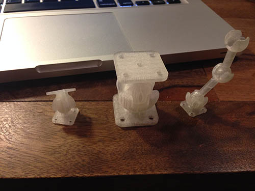
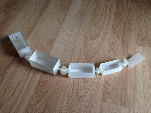
We decided to make a laser cut box to hold all our electronics, and to support the ‘goose-necks’ we plan to use to position and hold the actuators in place along with providing us flexibility. This box is now designed and we have a 2nd prototype of it- there are three compartments: The 1st compartment holds the Udoo, the 2nd houses the 50W x 2 Audio Amp and the 3rd holds the battery and the power/driving circuitry.

The box is strong enough to hold the weight of the goose-necks and the actuators. All sides are ‘interlocking’ except for one. This side allows service of inner electronics, as required.

The top and bottom of the box are cut with a thicker sheet of Masonite, as these would support the box or the actuators. So the plan is to allow this box to be attached to any 1/4 inch 20 bolt holder (like all tripods) so it can attach to whatever support we want. To distribute the weight, we will thread a 1/4 inch 20 into a metal sheer (similar to the template you can see in the diagram) and cut it so as to bind it to the lower side of the box. The top of the box already has space for attaching 4 actuators, as the four holed allow 4 goose-necks to be attached- we wouldn’t use more than 2 for now.

All the hardware required (screws, bolts, nuts) have been ordered.

IMG_0343

Udoo, actuators
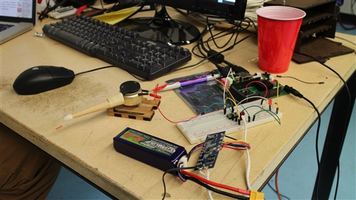
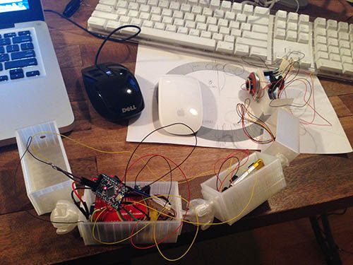
Our initial tests with the actuators used simple transistors connected directly to a DC power supply. This week we were able to connect a striker to the Udoo, and control it using a simple PureData software interface to the Udoo’s GPIOs.

Specifically, our striker actuator is connected to a DRV8835 dual motor driver, which uses logical power from the Udoo, and motor power from a battery back. We’ll need two of these motor drivers for each cricket, each of which will control four actuators.

The video below shows our basic setup. The next step is to make the circuitry more robust and portable, so that we can quickly scale to more actuators in week 3.
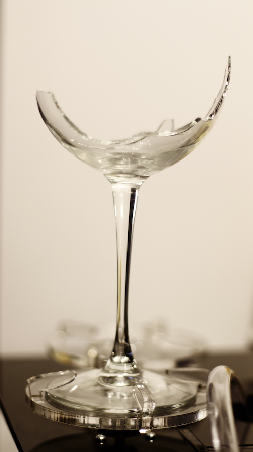
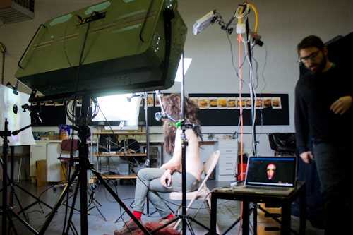
IMG_0340

Final Project Milestone 2 – Can Ozbay

Final Project — Can Ozbay @ 6:17 pm

IMG_1322 IMG_1315photo 3


Final Project Milestone 2 and 3 – JaeWook Lee

Final Project — jwleeart @ 6:11 pm


sm02IMG_5930 IMG_5948  sm09

ideasthesia installation view from JaeWook Lee on Vimeo.

Final Project Milestone 2 – Sean Lee

Assignment,Final Project — Sean @ 3:59 pm

to make a shape and circuit

After making the connection of bluetooth, I have worked to make a shape and circuit. For building the shape, I have to decide how to hold and change between a headphone and speaker shape because my previous shape has a potential to be changeable, but it’s not enough to hold a headphone unit without a support. However, one labmate gave a hint to use a joint and socket structure and I did it with Makerbot 3D printer.

photo (5)

And, then I made a quick and dirty shape not for final first because I have to wait some parts from Sparkfun for making the final circuit and I wanted to test and measure how I can deploy parts into the shape.

photo (4)

photo (3)

Until, now, I have a serious problem about unstable datas from analog sensors because the circuit structure requires a little complexity and I don’t have enough experience. So, probably, in this week, before making final version, I have to make sure this issue.

Appendix.

I have tried many types of sensors as the input part such with a Potentiometer and joystick and touch pad. During this process, what I found is that every sensors bring different situations and responses from users. For example, Joy stick causes more an active interaction than others and touch pad seems more like a play and stop button although both have much more freedom than a potentiometer.

Final Project Milestone 2 – Jake Marsico

Assignment,Final Project,Max,Uncategorized — jmarsico @ 1:21 pm

_MG_2036

The Shoot

This past weekend I finished the video shoot with The Moon Baby. Over the course of three and a half hours, we shot over 80 clips. A key part of the project was to build a portrait rig that would allow the subject to register her face at the beginning of every clip. The first prototype of this rig consisted of a two way mirror that had registration marks on it. The mirror prototype proved to be inaccurate.

The second prototype, which we used for the shoot, relied on a direct video feed from the video camera, a projector and a projection surface with a hole cut out for the camera to look through.


At the center of this rig was a max/msp/jitter patch that overlayed a live feed from the video camera on top of a still “register image”. This way, the subject was able to see her face as the camera saw it, and line up her eyes, nose, mouth and makeup with a constant still image. See an image of the patch below:

max_screenshot


The patch relied on Blair Neal’s Canon2Syphon application, which pulls video from the Canon dslr’s usb cable and places it into a syphon stream.  That stream is then picked up by the max/msp/jitter patch.

Here is a diagram of the entire projection rig:

Woo portrait setup

Soon into the shoot, we realized a flaw with the system: the Canon camera isn’t able to record video to its CF card while its video feed is being sent to the computer.  As a result, we had to unplug the camera after the subject registered her face, record the clip, then plug the camera back in.  We also had to close and reopen Canon2Syphon after each clip was recorded.

SONY DSC

Wide shot of the entire setup.


To light the subject, I used a combination of DMX-controlled fluorescent and LED lights along with several flags, reflectors and diffusers.


Final Project Milestone 2 – Spencer Barton

Final Project,Rhino3D,Scanning — spencer barton @ 12:34 am

A Walk in the Woods

In the first milestone I defined five options for objects to capture. I decided to go with ‘A Walk in the Woods’:

I grew up playing in the woods. It was always an adventure – new bugs lay under every rock and dirt could be molded into innumerable forts. I have gradually left the woods behind (as I imagine most of us are doing these days). My goal is to take a simple walk through the woods and record any and all interesting discoveries that I make. These critters, rocks and leaves would then be created as physical models to capture some of that excitement of discovery.

Captures and Lessons Learned

I have performed a number of captures now, some with great success and others with less.

I have a few pointers for capture:

  • Lighting if important. Diffused light works better then a spotlight. Captures did well with just the microscope light on.
  • The angle of capture cannot be too deep. The objects did best at 30-45 degrees.
  • The object surroundings are very important as background objects help the software orient the images. Latter models all have orange clay bases for support and textured background.
  • 30x magnification worked well for the objects that I had. Captures work best when the capture can see a wide range of the object’s surroundings
  • Taking pictures at different focus depths came out well.
  • The more pictures the better. I usually took 40-70.
  • Shiny objects don’t do as well
  • Small details like bug legs are rarely captured.

Here are some of the results (all models available on my 123D account):

Future Steps

The next hurdle is manufacturing. I am exploring two options. One in 3D printing in plaster. The d-fab on campus has the ability to print color plaster models.

I am also looking into 123Dmake which converts designs to layered models which can then be cut in something like cardboard. This would enable me to create some very large models.

« Previous PageNext Page »
This work is licensed under a Creative Commons Attribution-Noncommercial-Share Alike 3.0 Unported License.
(c) 2025 Hybrid Instrument Building 2014 | powered by WordPress with Barecity