1. My boards arrived!!
After about 12 days, OSH Park fabricated and delivered my boards. Yes, they are fantastic purple and look like exactly what I expect. I soldered and assembled every components together to test the board. Finally, all boards work with all the components but the transistor. I used smaller one instead of TIP 120. For some reason, it could work with Trinket board. So, I used TIP 120 again with my final board.

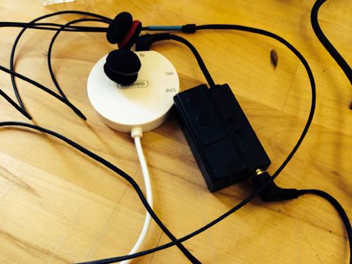
2. Add Microphone Module!
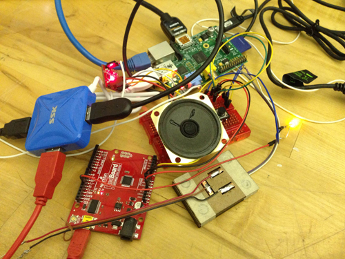
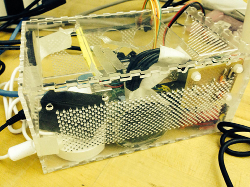
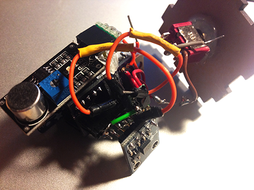
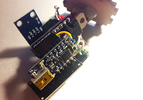
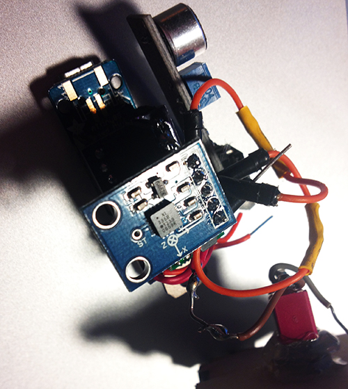
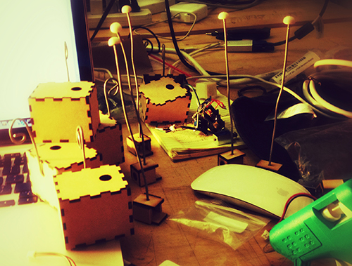
To solve the problem of gestures and how user interacts with cup and Tapo, I decided to use a microphone to record user’s input (oral rhythm, voice, and even speech). The idea is quite simple: since the electret microphone turns analog voice data into digital signal, I can just make use of the received signal and generate certain beat for a rhythm. That is more reasonable interaction for users and my gestures can be put into two categories: trigger the recording and clear the recorded rhythm. The image below shows the final look of the hardware part, including the PCB board, Trinket board, transistor, step-up voltage regulator, solenoid, accelerometer, electret microphone, and a switch.
3. Fabrication!
All parts should be enclosed in a little case. At the beginning I was thinking of 3D printing a case and using magnets to fix the case on the cup. I 3D printed some buckets with magnet to see the magnetic power. It seemed not very well in attracting the whole case. The other thing looks difficult for 3D printing case was that it was not easy to put the entire hardware part in and get it out.
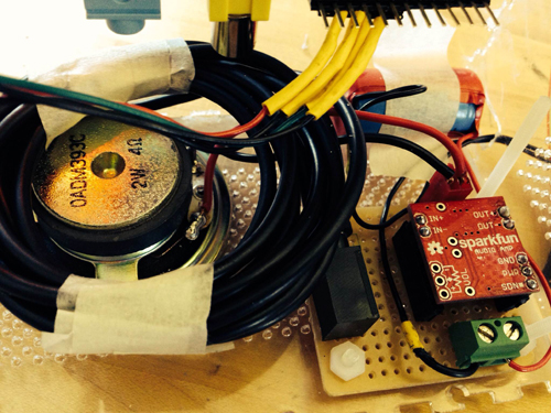
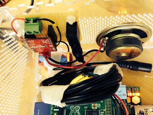
Then I focused on laser cutting. I created a box for each unit and drilled one hole for solenoid, one hole for microphone and a hole for hook. I experienced three versions: the first one left one hole for the wire of solenoid to go through, thereby connecting with the main board. But the solenoid could not be fixed quite well (I used strong steel wire to support it); The second version put the solenoid inside the box and opened a hole on the back facet, so that it could tap the cup it was mounted on, but the thickness of the box avoided the solenoid to touch object outside; In the final version I drilled a hole on the upper plate for the switch, and modified the construction for solenoid.
Version 1

Version 2
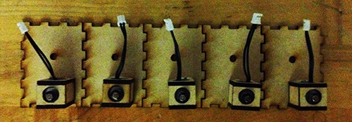
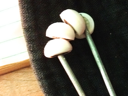
Solenoids
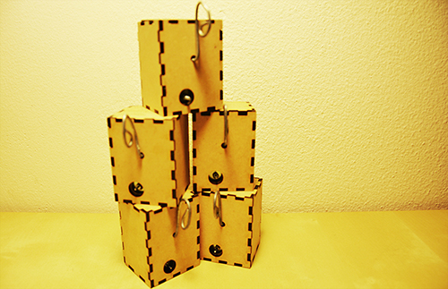
Version 3
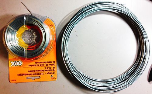
Another thing is the hook. I started with a thick and strong steel wire and resulted in that it could not be bended easily. Then I used a thinner and softer one, so that it could be bended to any shape as the user wished.
4. Mesh up codes and test!!
Before program the final unit, I programmed and tested every part individually. The accelerometer and the gestures worked very well, the solenoid worked correctly, and I could record user’s voice by microphone and transferred it to certain pattern of beats. Then the challenge is how to make a right logic for all the things work together. After several days’ programming, testing, debugging, I meshed up all logics together. The first problem I met was the configuration of Trinket, which led to my code could not be burned to the board. Then the sequence of different module messed up. Since the micro controller processed data and events in a serial sequence, so the gesture data could not be “timely” obtained while the beats of solenoid depended on several delays.
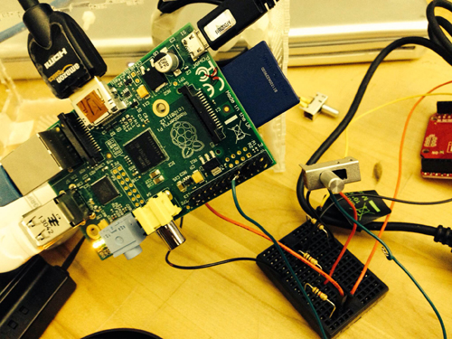
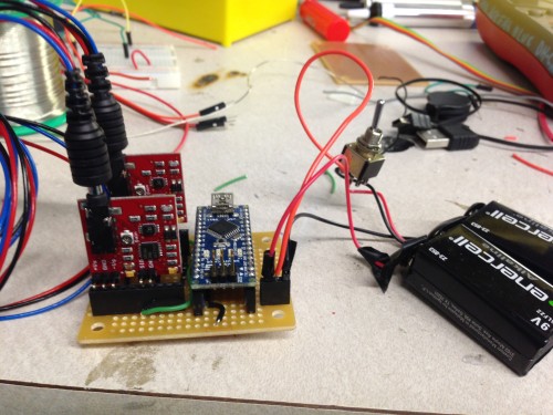
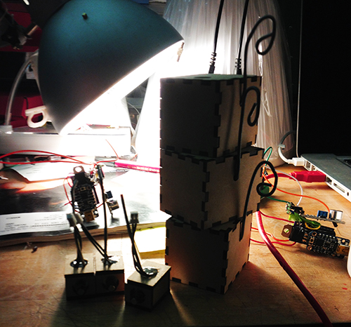
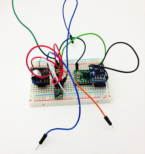
I built a similar circuit, in which my custom PCB was replaced by a breadboard, to test my code. In the test, I hoped to check if my parameters for the interval of every piece of rhythm was proper, if the data number of the gesture set was enough to recognise gestures, if specific operation causes specific events, and most importantly, if the result looked good and reasonable.
Here is the test unit:
Here is a short video demo of the test: