Final Project Milestone One: Jake Berntsen

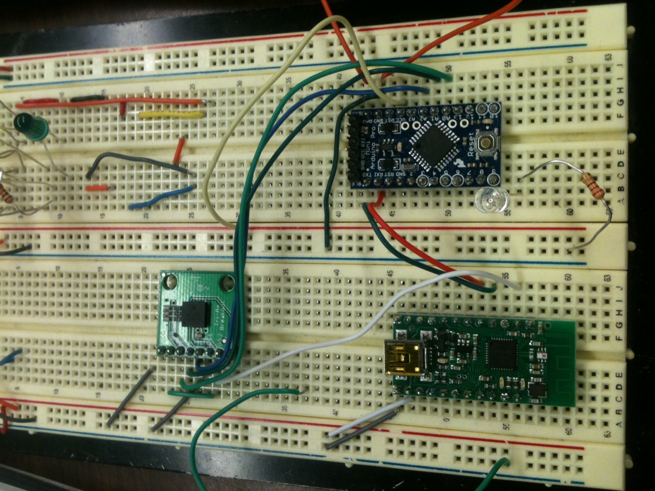
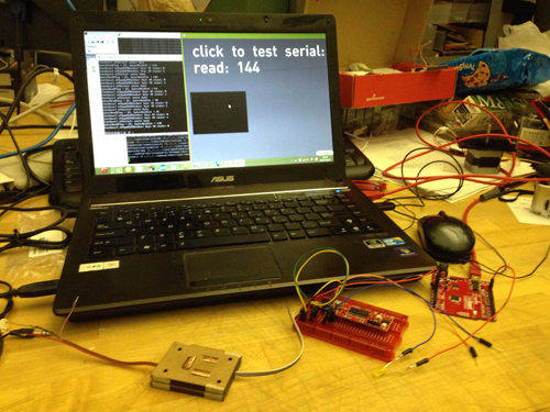
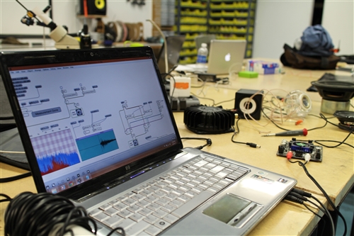
My struggles thus far in this class have rested almost entirely on the physical side of things; I’m relatively keen with regards to using relevant software, but my ability to actually build devices is much less developed, to say the least.  With this in mind, I decided to make my early milestones for my final project focus entirely on the most technically challenging aspects in terms of electrical engineering; specific to my project, this meant getting all of the analog sensors running into my Teensy to obtain data I could manipulate in Max.  To do so meant a lot of prototyping on a breadboard.

IMG_1449

After exploring a wide variety of sensors, I found a few that seemed to give me a sharp control of the data received by Max.  One of my goals for this project is to create a controller that offers a more nuanced musical command than the current status quo, and I believe that the secret to this lies within more sensitive sensors.


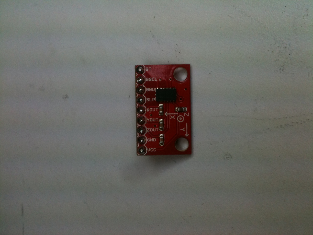
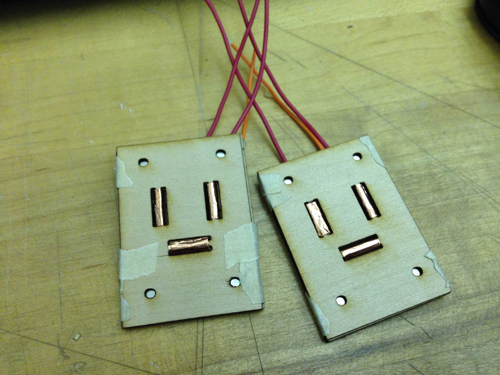
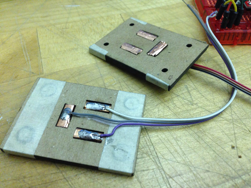
The sensors I chose are picture below: Joysticks, Distance Sensors, Light Sensors, and a Trackpad.

Joystick


Light Sensor


IMG_1445


IMG_1447


All of the shown sensors have proven to work dependably, with the exception of some confusion regarding the input sensors of the trackpad.  The trackpad I am using is from the Nintendo DS gaming device, and while it’s relatively simple to get data into Arduino, I’m having trouble getting data all the way into Max.

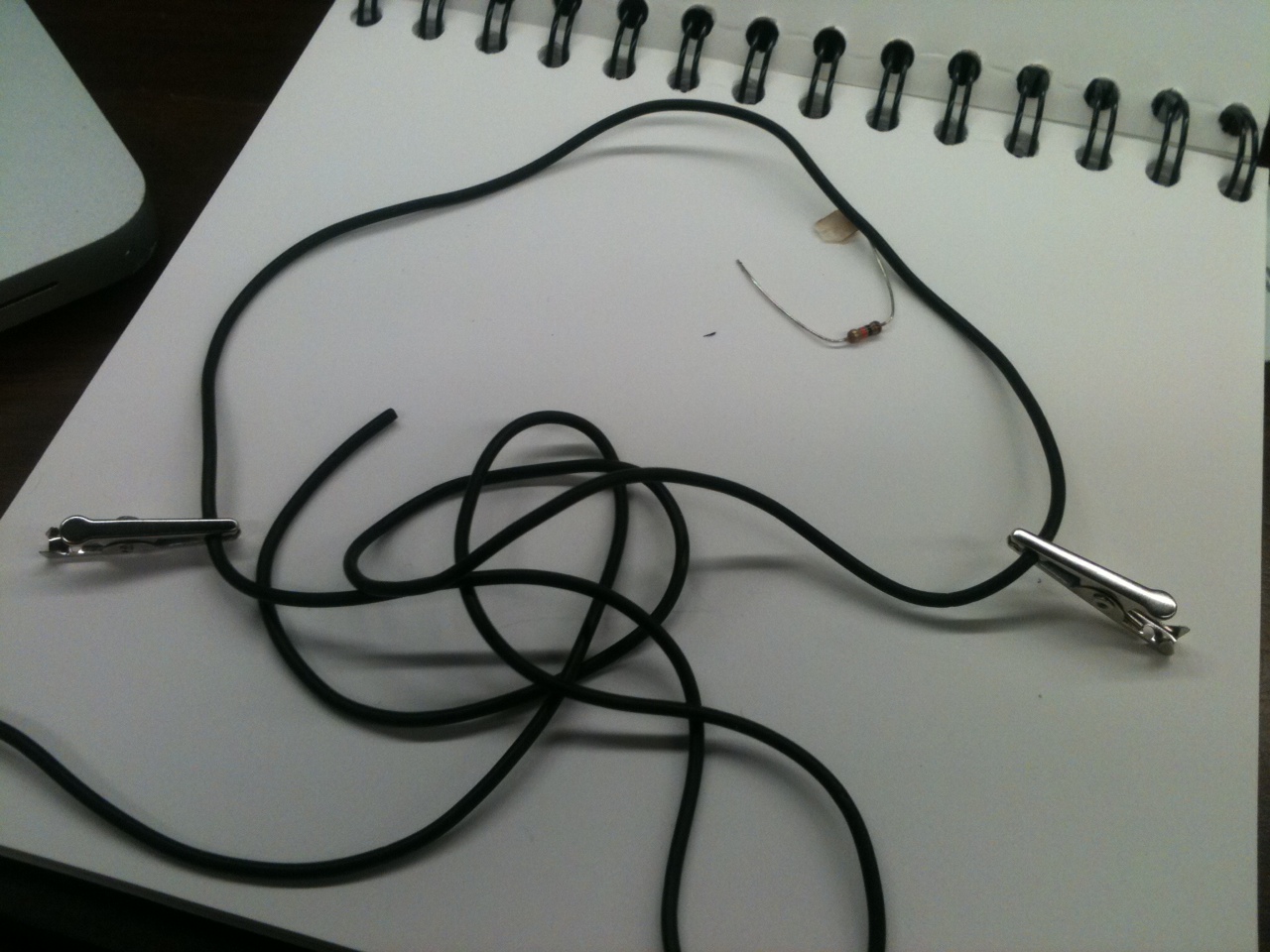
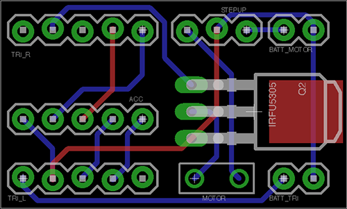
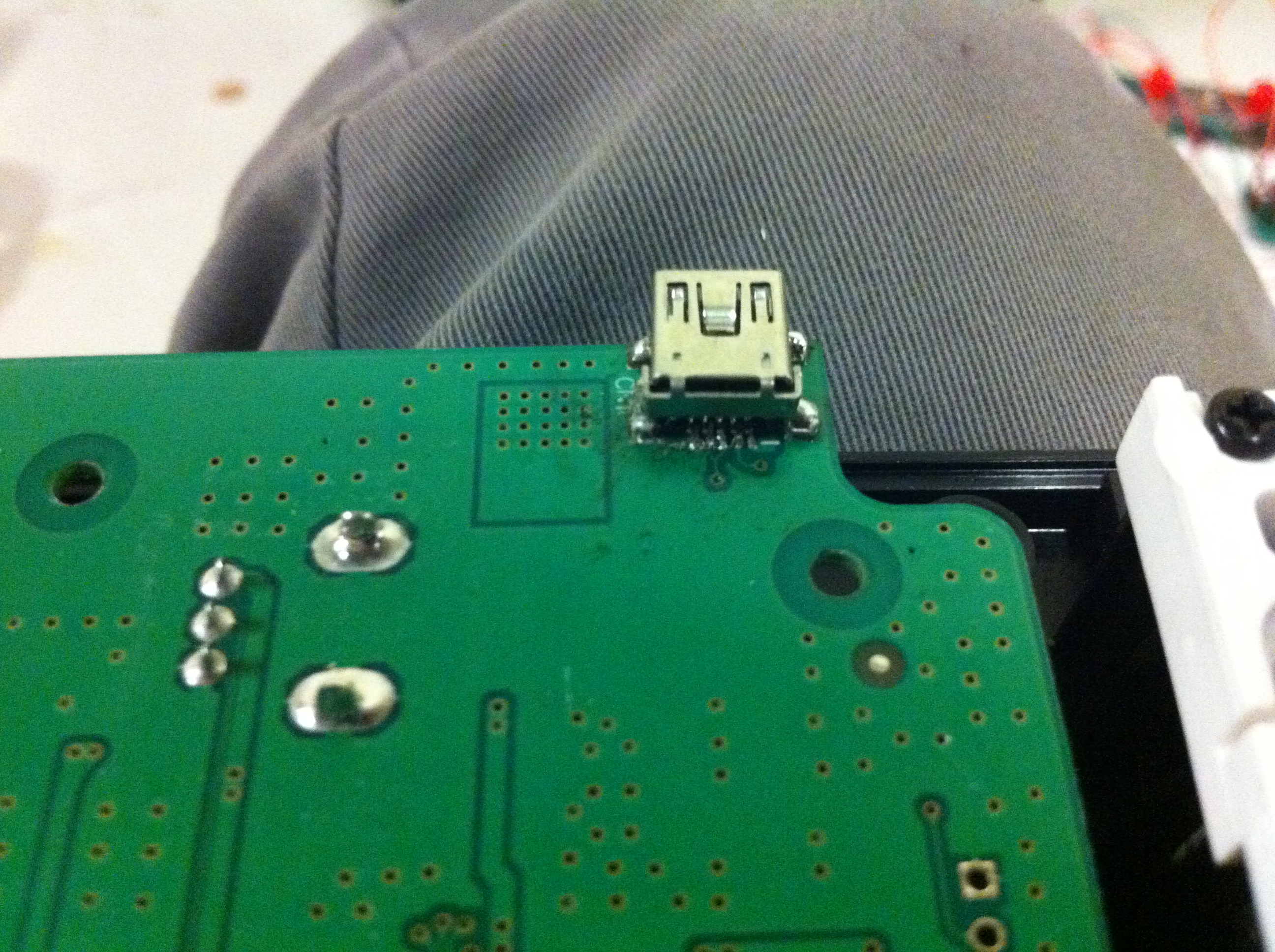
The other hardware challenge that I was facing this week was fixing the MPK Mini device that I planned to incorporate into my controller.  The problem with it was a completely detached mini USB port that is essential to the usage of the controller.  Connecting a new port to the board is a relatively simple soldering job, and I successfully completed this task despite my lack of experience with solder.  However, connecting the five pins that are essential for getting data from the USB is a much more complicated task, and after failing multiple times, I decided to train myself a bit in soldering before continuing.  I’ve not yet seen success, but I’ve improved greatly in the past few days alone and feel confident that I will have the device working within the week.

IMG_1451

IMG_1450


If I continue working at this rate, I do believe that I will finish my project as scheduled.  While I was anticipating only being able to use the sensors that I could figure out how to use, I instead was able to make most of the ones I tried work with ease and truly choose the best one.

IMG_1452

Final Project Milestone 1 – Job Bedford

Assignment,Final Project,Uncategorized — jbedford @ 11:53 am

Project: SoundWaves – Wearable wireless instrument enabling user to synthesis rhythmic sounds through dance.

Milestone 1 Goal:
Decide on Sensors and music playing software.

Sensors:
Decided to use: Conductive Rubber, Accelerometers, and homemade force-sensative resistors.

photo-42
photo-58
photo-67

Video:

Prototyping:

Prototype 1:
Bread Board
photo-39

Perf Board

photo-40

Prototype 2:
Used CNC router to cut boards
photo-43

photo-37

Fail. CNC router is not precise enough to cut traces of 24 mils with clearance from each other. Easier to make perf boards(I am considering print PCB’s from commercial Board maker.)

photo-41

Hardware: Mounting upon Shinguards. Force sensitive resistors in Shoes. Dance is more about Lower body movement than upper body movement

Music Playing Software:
Choices
Synthesised Audio: Max_instruments_PeRcolate_06 – traditional instruments artificially reproduced in max, with a level of sensitivity to adjust elements such as pitch, Hardness, Reed stiffness, etc. Denied due to lack of quick adjustablilty to changes in values, still under consideration.

Samplers: Investigated use of free samplers such as Independence and SampleTank, but samplers became to convoluted to setup and the trail for free use expires after 10 days. Denied

Insystem Samplers: Audio DSL synth using midi-out Function in Max. over complicated. Denied.

Resonator/Wikonator: Still under consideration.

Simple Hardcoded Max mapping of gestures to sounds and sound files of 808 drum machine: Accepted.

Wireless:
Wixel are useful, but can only hook up one channel to system, can not read multiple channels on same line, or else getting confusing serial readings.
Bluetooth, Personalize channels but expensive.
Bluetooth and Wixel combination, under consideration.

Final Project Milestone 1 – Mauricio Contreras

Assignment,Final Project,Robotics,Submission,Technique — mauricio.contreras @ 11:45 am

My first milestone was to procure myself all the software tools necessary for at least simulating motion of a robotic arm within a framework which has been previously used by Ali Momeni. Namely, this means interacting with Rhinoceros 3D, the Grasshopper and HAL plugins, and ABB RobotStudio. I’ve now got all this pieces of software up and running in a virtual image of Windows (of the above only Rhino exists, as a beta, for OS X) and have basic understanding of all of them. I had basic dominion of Rhino throuh previous coursework, and now have done tutorials fro Grasshopper by digitaltoolbox.info and the Future CNC website for HAL and RobotStudio. I’ve got CAD files that represent the geometry of the robot, can move it in freehand with RobotStudio and am learning to rotate the different joints in Rhino from Grasshopper.

Update (12/11/2013): added presentation used the day of the milestone critique.

Final Project Milestone 1 – Ding Xu

We live in a world surrounding by different environments. Since music could have mutual influence with human’s emotions, environments also embrace some parameters which could get involved in that process. In certain content, environment may be a good indicator to generate certain “mood” to transfer into music and affect people’s emotions. Basically, the purpose of this project is to build a portable music player box which could sense the surrounding environment and generate some specific songs to users.

This device has two modes: the search mode and generate mode. In the first mode, input data will be transformed into some specific tags according to its type and value; then these tags are used to described a series of existing songs to users. In the second mode, two cameras are used to capture ambien images to create a piece of generative music. I will finish the second mode in this class.

In mode 2, for each piece of song, two types of images will be used. The first one is a music image captured by an adjustable camera and the content of this image will be divided into several blocks according to their edge pixels and generate several notes according to their color. The second image is a texture one captured by a camera with a pocket microscope. When the device is placed on the different materials, corresponding texture will be distinguished and attach different instrument filter to music.

Below is a list of things I finished in the first week:

  • System design
  • platform test and select specific hardware and software for project
  • Be familiar with raspberry pi OS and Openframeworks
  • Experiment about data transmission among gadgets
  • Serial communication between arduino/teensy and Openframeworks
  • get a video from camera and play sound in openframeworks

Platform test:

Since this device is a portable box which need to be played without supporting of a PC,  therefore, I want to use raspberry pi, arduino and sensors (including camera and data sensors) to do this project. As for the software platform, I chose openframeworks as the maor IDE and plan to use PD to generate sound notes, connecting it with openframeworks for control. Moreover, it’s more comfortable for me to use C++ rather than python, since I spent much more time to achieve some a HTTP request to log into Jing.FM in python.

Python test

Raspberry Pi Network setting

As a fresh hand for Raspberry Pi without any knowledge about Linux, I got some problems when accessing into the CMU-secure wifi with Pi since the majority of tutorial is about how to connect the Pi with a router, and CMU-secure is not the case. Finally, I figured it out with the help of a website explaining the very specific parameters in wpa_supplicant.conf, the information provided by CMU computing service website and copying the certificate file into Pi. I also want to mention that each hardware which use CMU wifi need to register the machine in netreg.net.cmu.edu/ and this process takes effect after 30 minutes.

Raspberri Pi

Data Transmission between gadget and arduino

Experiment 1: Two small magnets attached in the gadget with the height of 4 mm

gadget1

gadget

Experiment 2: Four magnets attached in the gadget with the height of  2.9 mm and 3.7 mm

gadget2


gadget3

the prototype 2 is easier to attach the gadgets together but all of these gadgets fail to transmit accurate data if not pressing the two their sides. A new structure is required to build to solve this problem.

Connecting arduino with openframeworks with serial communication

Mapping 2 music to different sensor input data value

OF test2

Final Project Milestone 1 – David Lu

Assignment,Final Project — David Lu @ 11:34 am

2013-10-28_20-58-19_897

Milestone 1: make sensors
The left circle has a force/position sensitive resistor, the black thing along the perimeter. The right circle has 3 concentric metal meshes with a contact mic in the middle. The metal meshes sense change in capacitance (ie proximity of my finger) when connected to the Teensy microcontroller.

Final Project Milestone 1 – Ziyun Peng

Assignment,Final Project,Max,Sensors — ziyunpeng @ 10:45 am

My first milestone is to test out the sensors I’m interested in using.

Breath Sensor: for now I’m still unable to find any off-the-shelf one which can differentiate between inhale and exhale. Hence I went to the approach using homemade microphone to get audio and using Tristan Jehan‘s analyzer object with which I found the main difference of exhale and inhale is the brightness. Nice thing about using microphone is that I can also easily get the amplitude of the breath which is indicating the velocity of the breath.  Problem with this method is it needs threshold calibration each time you change the environment and homemade mic seems to be moody – unstable performance with battery..

mini-mic

breath

Breath Sensor from kaikai on Vimeo.

Muscle Sensor:  It works great on bicep although I don’t have big ones but the readings on face is subtle – it’s only effective for big facial expressions – face yoga worked. It also works for smiling, opening mouth, and also frowning (if you place the electrodes just right). During the experimentation, I figure it’s not quite a comfortable experience having sticky electrodes on your face but alternatives like stretching fabric + conductive fabric could possibly solve the problem which is my next step. Also, readings don’t really differentiate each other, meaning you won’t know if it’s opening mouth or smiling by just looking at the single reading. Either more collecting points need to be added, or it could be coupled with faceOSC which I think is more likely the way I’m going to approach.

EMG_faces

FaceOSC: I recorded several facial expressions and compared the value arrays. The results show that the mouth width, jaw and nostrils turned out to be the most reactive variables. It doesn’t perform very well with the face yoga faces but it does better job on differentiating expressions since it offers you more parameters to take reference of.

faceOSC_faces

Next step for me is to keep playing around with the sensors, try to figure out a more stable sensor solution (organic combination use) and put them together into one compact system.

Final Project Milestone 1 – Haochuan Liu

Assignment,Audio,Final Project,OpenCV — haochuan @ 10:28 am

Plan for milestone 1

The plan for milestone 1 is to build the basic system of the drawable stompbox. First, letting the webcam to capture the image of what you have drawn on paper, then the computer can recognize the words on the image. After making a pattern comparison, the openframwork will send a message to puredata via OSC. Puredata will find the right effect which is pre-written in it and add it to your audio/live input.


milestone 1 plan


Here is the technical details of this system:

Screen Shot 2013-10-30 at 4.53.23 PM

After writing words on a white paper, the webcam will take a picture of it and then store this photo to cache. The program in OpenFrameworks will load the photo, and turn the word on the photo to a string and store it in the program using optical character recognition via Tesseract. The string will be compared to the Pattern library to see if the stompbox you draw is in the library. If it is, then the program will send a message to let PureData enable this effect via OSC addon. You can use both audio files or live input in puredata, and puredata will add the effect what you have drawn to your sound.

Here are some OCR tests in OF:

test1-result test2-result test3-result test4-result test5-result test6-result


About the pattern library on OF:

After a number of test for OCR, the accuracy is pretty high but not perfect. Thus a pattern library is needed to do a better recognition. For example, Tesseract always can not distinguish “i” and “l”, “t” and “f” , and “t” and “l”. So the library will determine what you’ve drawn is “Distortion” when the result after recognition is “Dlstrotlon”, “Disforfion” or “Dislorlion”.

Effects in PureData:

Until now, I’ve made five simple effects in PureData, which are Boost, Tremolo, Delay, Wah, and Distortion.

Here is a video demo of what I’ve done for this project:

Hybrid Instrument Final Project Milestone 1 from Haochuan Liu on Vimeo.


Final Project Milestone 1 – Robert Kotcher, M. Haris Usmani

Assignment,Final Project — Usmani @ 10:06 am

Robert and I set forth to complete the following tasks in this first week:

  • Experiment with different actuators
  • Explore the sounds we can make
  • Explore how rooms may sound differently
  • Get recordings and play with some DSP to get an understanding of things

We pretty much got through most of that, but the phase of exploration is a never ending one- we now have the prototypes we need to play around and explore sounds in different rooms, like we did this week for our class-room.

Exploring Actuators:
We considered three actuators to start with:
i) Loud speakers 2) Audio Transducers

The loud speaker and the audio transducer were to be fed by an audio signal convoluted with the class-room’s impulse response (IR). This would (in theory) make a room’s reverb twice as effective and would result in the ‘interesting’ resonant effects we need. First, this required the room’s IR to be found- we found HISSTools to be very helpful. We were able to get example patches that used HISSTools to capture IR of a room.

Spatianator - 1_1

Exponentials were sweeped across the frequency range and the response recorded and processed. Once we had the IR, we simple convolved it with our audio signal and played it back to the room using speakers we had: Studio Monitors in this case.

Spatianator - 1_2

We observed that the low-frequency resonance gets very strong and it seems to trace and amplify the right frequencies to literally “shake the room”.


To explore what the high-end resonance would sound like, we used an open mid-range speaker (with a weak bass response as it had no enclosure).

Spatianator - 1_3

It seemed to produce more of a high ringing noise but less drastic effects than that of the low frequency resonance.

3) Electromagnetic Striker:

Spatianator - 1_4

The prototype Striker actuator was built using a Teensy, rotary solenoid and drumstick with a nylon head. We experimented with a variety of striking objects, but found that this drumstick was light and was able to characterize the room nicely, without the drumstick itself sounding too loudly.

Spatianator 1_5

An issue we’re facing now is the solenoid making sounds of its own. We may be able to modify it or use a different type of solenoid. A final prototype will consist of a self-contained and portable actuator in an enclosed case, with a more refined attachment for the drum stick. While the software hasn’t been written yet, it will instruct the solenoid to play the room in response to the performer.

Learning Outcomes:

We plan to use the IR Response to assign characteristic sounds to our actuators- this mapping has yet to be tried and tested but we expect to get something interesting.

Also, we feel we need another actuator as the loud speaker or audio transducer are very similar as far as low frequency resonance is concerned. The transducer requires contact with the surface, so we may just choose the loud-speaker over it. A third actuator may be a scratcher.

To capture the true IR of the room, we may use a pair of balanced omni-directional microphones placed at the listener’s position in the room- right now, our cost-effective condenser mic isn’t giving us the true IR but is accurate enough to get things started.

Spatianator 1_6

Throughout the course of exploration, we also kept the bigger picture in mind- these are a few changes we made to the initial setup for a more cost-effective and convenient implementation:
– Raspberry Pi replaced with Udoo (Due to the Cost of Audio I/O and Wireless Access we require)
– Having a central PC that listens to the performer and ‘conducts’ the room (sends audio/controls to crickets)

These considerations will be given more though and design decisions will be made based on more experimentation.

Final Project Milestone 1 – Spencer Barton

Final Project,Scanning — spencer barton @ 8:00 am

The Project

Our world is defined by what we see. However beneath our feet exist an enormous and elaborate system of creations. With the aid of a microscope and camera I am seeking to recreate through 3D modeling the millimeter scale for the centimeter scale that we live in. This project is enabled by key advancements in 3D modeling software such at Autodesk’s 123D Catch.

The process for capture is fairly simple. A series of photographs are taken of an object from every direction. These photographs are stitched together and distance is interpolated resulting in a 3D model. The chair model below is a good illustration. About 40 photographs were taken from a variety of angles and then uploaded to 123D Catch.

Chair Test

Milestone 1

The goal of my first milestone was to create a functioning 3D scanning jig as well as perform some research into objects to capture.

Scanning Jig

The scanning jig is based around a microscope. I began with a usb microscope, but it quickly proved not to have the necessary image resolution.

Example of the USB microscope:

t4

The Original Microscope Jig

I discovered that my iPhone camera was high enough resolution with the added advantage of being easy to work with. I got hold of a microscope from the robotics club and set-up a few tests holding my camera to the lenses. I created a rotating stand for the object with a LEGO piece, tape and cardboard.

2013-10-23 20.52.32

Lessons Learned

From this first prototype I learned that it important to have a textured surface for the rotating base. The 3D capture software relies on picking out key points in each photo, so a textured base provides more unique points for the software. I also discovered the importance of a stable camera. The model below turned out poorly as camera jitter made depth interpolation difficult.

Piece of Solder

Upgraded Jig

The first jig was upgraded first with the use of magic arms for camera stabilization as well a a sturdier turning base. The base utilized the same LEGO piece but was planted in clay in order to make the assembly flexible. I wanted to be able to change platform height and angle easily.

The Photo Platform

2013-10-28 19.48.20

Jig Results: Acorn

What to Capture?

5 ideas on interesting things to capture. I will pursue one or more.

Food

Food doesn’t always look as nice close up. This project would provide a new perspective on good food at a new scale.

Chewed Gum

2013-10-28 20.26.19


A walk in the woods

I grew up playing in the woods. It was always an adventure – new bugs lay under every rock and dirt could be molded into innumerable forts. I have gradually left the woods behind (as I imagine most of us are doing these days). My goal with this track would be to take a simple walk through the woods (Schenley Park) and record any and all interesting discoveries that I make. These critters, rocks and leaves would then be created as physical models to capture some of that excitement of discovery.

A Rolly-polly Bug

2013-10-28 17.29.52


Surfaces

We have a good sense of how a surface might feel, but how does touch translate to the physical look of a material? Surfaces would be recreated in larger scale so that roughness becomes visibly rough and the finer details of materials like velcro can be seen.

Velcro

2013-10-28 20.18.29

Close-up

Inspiration for this track comes from hyper-realism. The goal here is to take a close-up look at less elegant human features. Following the lead from Ron Mueck, these captures would transformed into larger then life models.

A Fingernail

2013-10-28 19.09.35

Fluids

Water forms differently on different surfaces. This track would explore the interaction between water on various surfaces and under varying conditions (heat, vibration, pressure, sunlight). As a comparison other fluids such as oil could be used. 3D modeling is particularly interesting as the liquids would be forming distinct forms in 3 dimensions and not just in profile. 3D printing would be a viable option as the form matters more then material in this case.

Water on a Leaf

2013-10-28 17.25.13

Final Project Milestone #1: Liang

Assignment,Final Project,Hardware,Sensors — lianghe @ 5:21 am

Project: Tapo

Tapo is a tangible device encouraging people to create beats and perform percussion music with daily cups. What kind of beats it can produce? The volume of the liquid in the cup, the material of the cup and how people interact with the cup matter. The pitch and the timbre depend on the resonant property and the material of the cup. People’s gesture decides the speed or the pattern of the beat.

In the past one and a half week I accomplished every items listed for my first milestone.

1. System Design: I sketched the whole system design and labeled every component in the sketch.

system


2. Basic Diagram: Based on the system design, I finished the system diagram.

3. Quick Prototype: I have finished two prototypes so far. One is composed of a Trinket, a 1K resistor, a step-up regulator, a transistor (TIP 120), an accelerometer, a solenoid and a battery. The other one is different from this one by using a Teensy and a smaller transistor (FU3910) instead. These two prototypes are currently supported by a big battery set and USB power supply. In the final version I will replace by two separate batteries supporting the micro controller and the solenoid, also use all the tiny components in one enclosure. The Trinket version almost has the final look of this project except for the transistor and the batteries. However, the cheap board Trinket does support the Serial debug. Therefore, I built the second prototype by Teensy for the next phase: gesture’s detection with accelerometer.

milestone_pic1

Prototype 1

milestone_2

Prototype 2

The prototype 1 is implemented to test the solenoid and the prototype 2 combines solenoid and accelerometer, which converts the data of accelerometer into the speed of the solenoid. Both prototypes are testified that solenoid, accelerometer and the entire hardware configuration can work.

4. Circuit Design: In order to produce multiple devices, I customised a PCB board for all the hardware components, including batteries ports, solenoid interface, transistor, resistor, step-up regulator, and accelerometer.

PCB_final PCB_Schematics


5. Component Purchase: I did a research on every component I would use in this project and test several transistors and boards, listed a budget for the hardware that I need. I have all the parts at hand for just one prototype. Here is some links of my wanted components:

Trinket: www.adafruit.com/products/1500

Batteries: www.amazon.com/gp/product/B006N2CQSS/ref=oh_details_o00_s00_i00?ie=UTF8&psc=1

www.adafruit.com/products/1570

Solenoid: https://www.sparkfun.com/products/11015

« Previous PageNext Page »
This work is licensed under a Creative Commons Attribution-Noncommercial-Share Alike 3.0 Unported License.
(c) 2025 Hybrid Instrument Building 2014 | powered by WordPress with Barecity