Final Project Documentation: The Wobble Box

Assignment,Audio,Final Project,Laser Cutter,Max,Sensors — Tags: , , , — Jake Berntsen @ 5:16 pm

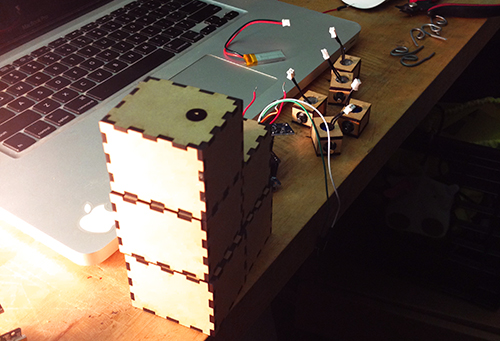
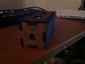
After taking time to consider exactly what I hope to accomplish with my device, the aim of of my project has somewhat shifted. Rather than attempt to build a sound-controller of some kind that includes everything I like about current models while implementing a few improvements, I’ve decided to focus only on the improvements I’d like to see. Specifically, the improvements I’ve been striving for are simplicity and interesting sensors, so I’ve been spending all of my time trying to make small devices with very specific intentions. My first success has been the creation of what I’m calling the “Wobble Box.”

IMG_1522

IMG_1524

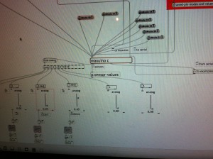
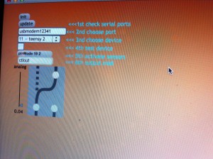
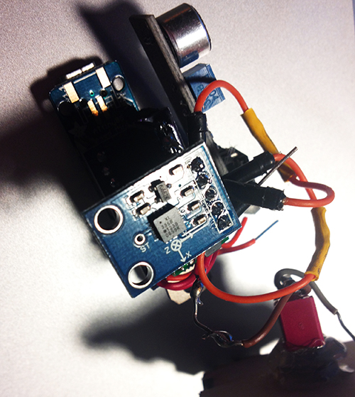
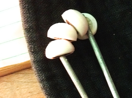
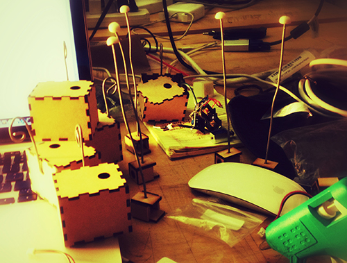
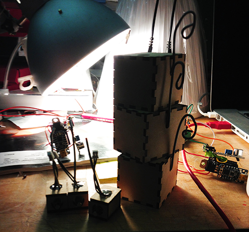
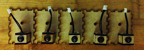
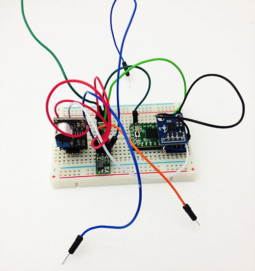
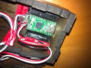
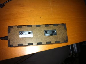
Simply stated, the box contains two distance sensors which are each plugged into a Teensy 2.0.  I receive data from the sensors within Max, where I scale it and “normalize” it to remove peaks, making it more friendly to sound modulation.  While running Max, I can open Ableton Live and map certain audio effects to parameters in Max.  Using this technique I assigned the distance from the box to the cutoff of a low-pass filter, as well as a slight frequency modulation and resonance shift.  These are the core elements of the traditional Jamaican/Dubstep sound of a “wobble bass,” hence the name of the box.  While I chose this particular sound, the data from the sensors can be used to control any parameters within Ableton.

IMG_1536

IMG_1535

IMG_1532

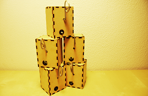
Designing this box was a challenge for me because of my limited experience with hardware; soldering the distance sensors to the board was difficult to say the least, and operating a laser-cutter was a first for me.  However, it forced me to learn a lot about the basics of electronics and I now feel confident in my ability to design a better prototype that is smaller, sleeker, and more compatible with similar devices.  I’ve already begun working on a similar box with joysticks, and a third with light sensors.  I plan to make the boxes connectible with magnets.
IMG_1528For my presentation in class, I will be using my device as well as a standard Akai APC40.  The wobble box is not capable or meant to produce its own melodies, but rather change effects on existing melodies.  Because of this, I will be using a live-clip launching method to perform with it, making a secondary piece of hardware necessary.
 

Final Project Milestone 3 – Can Ozbay

Assignment,Final Project — Can Ozbay @ 3:22 pm

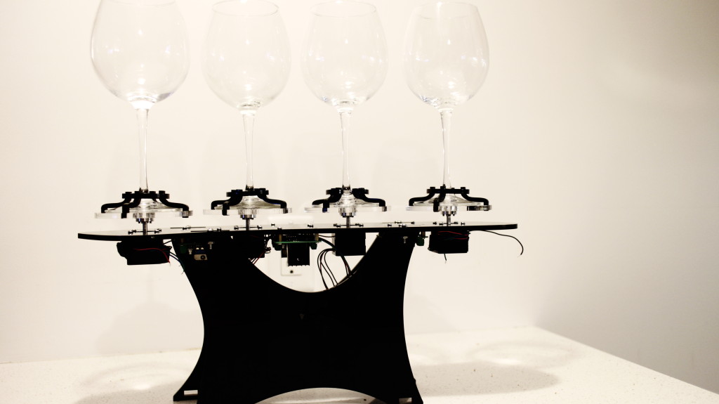
Based on the feedback I got, I’ve finished the second iteration of the design, which looks sleek, more packaged, and more portable.

Friction stick problem is mostly fixed, and I’ve changed the stick – glass distance to make it fit for the sponges.

Also to solve the crazy cabling problem I’ve created an Arduino Due(! yes “Due” – not duemilanove) Shield. Which I’m expecting to arrive from fabrication this week.

IMG_1591


IMG_1604

Conversus Vitra – Mainboard

Final Project Milestone 3: Jake Marsico

Assignment,Final Project — jmarsico @ 1:38 pm


Sequencing Software

The past two weeks were dedicated to building out the dynamic video sequencing software. As a primary goal of this project was to create seamless playback across many unique video clips, building a system with low-latency switching was key. Another goal of the project was to build reactive logic into the video sequencing.
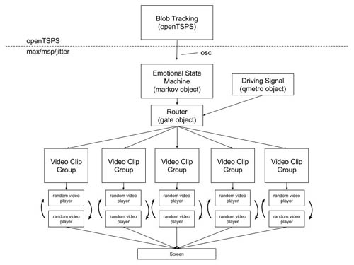
I will explain how I addressed both of these challenges later when I explain the individual components.  Below is a high-level diagram of the software suite.

Woo_app_diagram


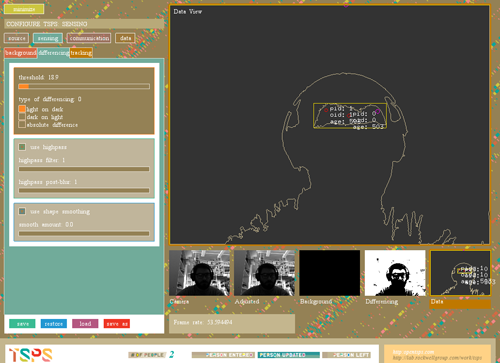
At the top of the diagram is openTSPS, an open source blob tracking tool built with openFrameworks by Rockwell Labs. openTSPS picks up webcam or kinect video, analyzes it with openCV and sends OSC packets that contain blob coordinates and other relevant events. For this project, we are only concerned with ‘personEntered’ events and knowing when the room is empty.

Screen Shot 2013-11-25 at 12.38.20 PMopenTSPS

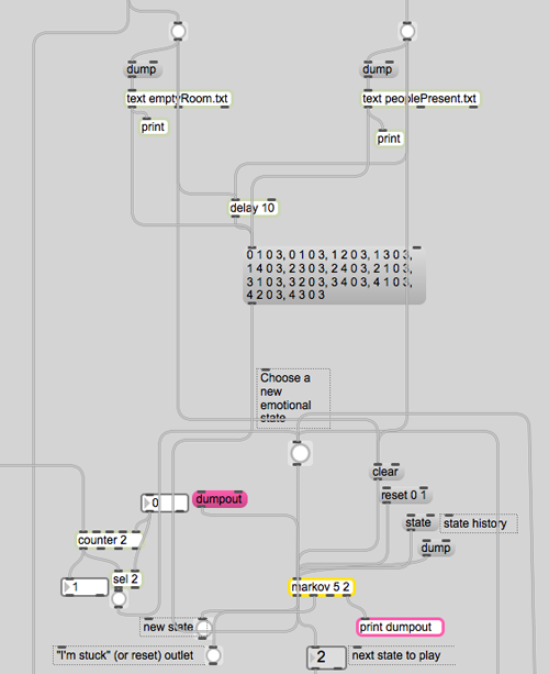
Blow openTSPS in the above diagram is the max/msp/jitter program, which starts with a probabilistic state machine that is used to choose which group of videos will play next. The state machine relies on Nao Tokui’s markov object, which uses a markov chain to add probability weights to each possible state change. This patch loads two different state change tables: one for when people are present and one for when the room is empty. This relates to a key idea of the project: that people act very differently when they are alone or around others.

Screen Shot 2013-11-25 at 12.29.00 PMstate transition with markov object

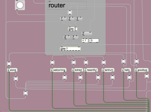
The markov state transition machine is connected to a router that passes a metro signal to the different video groups. The metro is called the ‘Driving Signal’ in the top diagram. The video playback section of the patch relies on a constantly running metro that is routed to one of seven double-buffered playback modules, which are labeled as emotional states according to the groups of video clips they contain.

Screen Shot 2013-11-25 at 12.34.28 PMrouter with video group modules

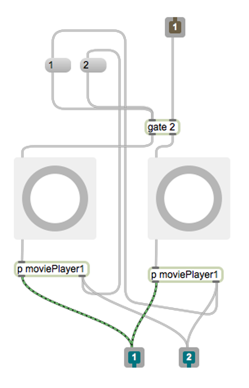
Each video group module contains two playback modules. The video group module controls which of the two playback modules is running.

Screen Shot 2013-11-25 at 12.34.54 PMvideo group module

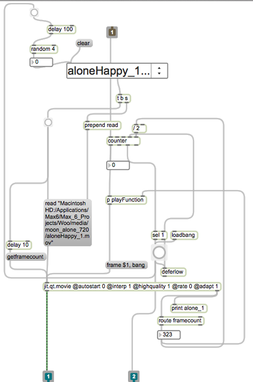
While one playback module is playing, the other one loads a new, random video from a list of videos.

Screen Shot 2013-11-25 at 12.35.09 PMplayback module

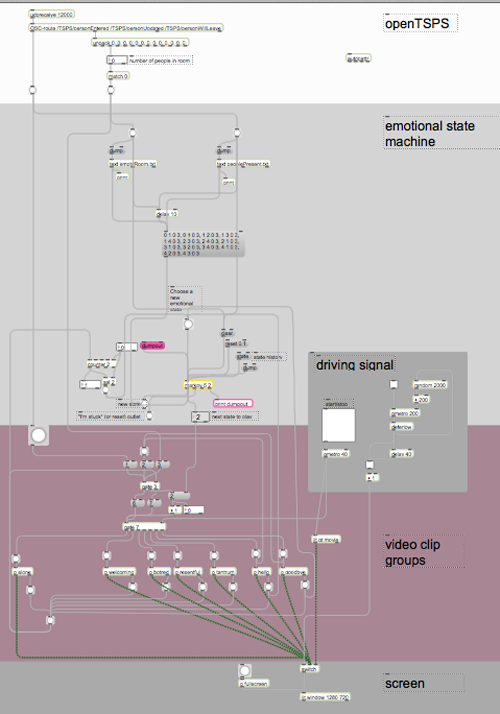
Here is a shot of the entire patch, from top to bottom:

Screen Shot 2013-11-25 at 12.28.31 PM“woo” max/msp/jitter patch


Challenges

The software works well on its own. Once connected to openTSPS’s OSC stream, it starts to act up. The patch is set up to bypass the state transition machine on two occasions: when a new person enters the room and when the last person leaves the room. To do this properly, the patch needs correct data from openTSPS. In its current location, openTSPS (paired with a PS3eye) is difficult to calibrate, resulting in false events being sent the application. One option is to build a filter at the top of the patch that only allows a certain number of entrances or ’empties’ within a given time period.  Another option is to find a location which has more controllable and consistent light.

Another challenge is that the footage was shot before the completion of the software. As a result, much of the footage seems incomplete and without emotion. To make the program more responsive to visitors, the clips need to be shorter (more like ~2 seconds each instead of ~9, which is the average for this batch).

Final Project Milestone #3: Liang

Final Project,Laser Cutter,Rhino3D,Sensors — lianghe @ 2:23 am

1. My boards arrived!!

After about 12 days, OSH Park fabricated and delivered my boards. Yes, they are fantastic purple and look like exactly what I expect. I soldered and assembled every components together to test the board. Finally, all boards work with all the components but the transistor. I used smaller one instead of TIP 120. For some reason, it could work with Trinket board. So, I used TIP 120 again with my final board.

photo


2. Add Microphone Module!

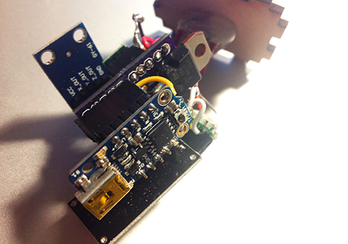
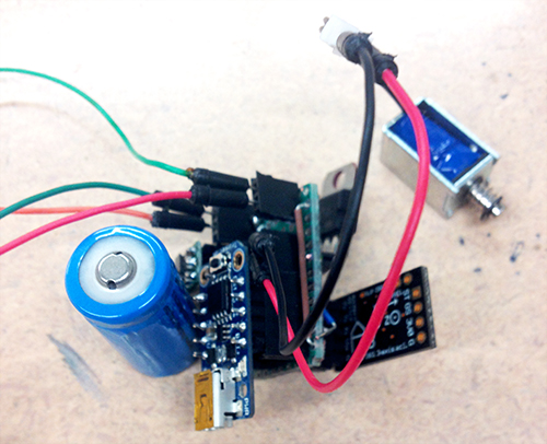
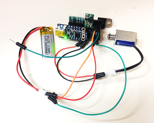
To solve the problem of gestures and how user interacts with cup and Tapo, I decided to use a microphone to record user’s input (oral rhythm, voice, and even speech). The idea is quite simple: since the electret microphone turns analog voice data into digital signal, I can just make use of the received signal and generate certain beat for a rhythm. That is more reasonable interaction for users and my gestures can be put into two categories: trigger the recording and clear the recorded rhythm. The image below shows the final look of the hardware part, including the PCB board, Trinket board, transistor, step-up voltage regulator, solenoid, accelerometer, electret microphone, and a switch.

photo

photo1


photo2


3. Fabrication!

All parts should be enclosed in a little case. At the beginning I was thinking of 3D printing a case and using magnets to fix the case on the cup. I 3D printed some buckets with magnet to see the magnetic power. It seemed not very well in attracting the whole case. The other thing looks difficult for 3D printing case was that it was not easy to put the entire hardware part in and get it out.

photo copy

Then I focused on laser cutting.  I created a box for each unit and drilled one hole for solenoid, one hole for microphone and a hole for hook. I experienced three versions: the first one left one hole for the wire of solenoid to go through, thereby connecting with the main board. But the solenoid could not be fixed quite well (I used strong steel wire to support it); The second version put the solenoid inside the box and opened a hole on the back facet, so that it could tap the cup it was mounted on, but the thickness of the box avoided the solenoid to touch object outside; In the final version I drilled a hole on the upper plate for the switch, and modified the construction for solenoid.

photo

photo copy


Version 1

photo copy

Version 2

photo copy

Solenoids

DSC_0110 copy1

Version 3

Another thing is the hook. I started with a thick and strong steel wire and resulted in that it could not be bended easily. Then I used a thinner and softer one, so that it could be bended to any shape as the user wished.

photo copy

4. Mesh up codes and test!!

Before program the final unit, I programmed and tested every part individually. The accelerometer and the gestures worked very well, the solenoid worked correctly, and I could record user’s voice by microphone and transferred it to certain pattern of beats. Then the challenge is how to make a right logic for all the things work together.  After several days’ programming, testing, debugging, I meshed up all logics together. The first problem I met was the configuration of Trinket, which led to my code could not be burned to the board. Then the sequence of different module messed up. Since the micro controller processed data and events in a serial sequence, so the gesture data could not be “timely” obtained while the beats of solenoid depended on several delays.

I built a similar circuit, in which my custom PCB was replaced by a breadboard, to test my code. In the test, I hoped to check if my parameters for the interval of every piece of rhythm was proper, if the data number of the gesture set was enough to recognise gestures, if specific operation causes specific events, and most importantly, if the result looked good and reasonable.

Here is the test unit:

photo copy

Here is a short video demo of the test:

Final Project Milestone 2 – David Lu

Assignment,Submission — David Lu @ 11:21 pm

Milestone 2: make my computer understand the sensors

It was working but then I tore everything apart and forgot to take documentation, oops. BRB putting everything back together.

Before sending the contact mic signal into the computer, it needed to be amplified. ArtFab had some piezo preamps lying around but they required 48v phantom power and I didn’t want to deal with that so I made my own preamp.

Final Project Milestone #2: Liang

Uncategorized — lianghe @ 11:06 pm

According to design critique from three guests, I rethought the scenarios and target user group. Instead of making tempos, I believe Tapo could produce more for users, for example, rhythms. Yes, with different cups and different resonance, it could generate various rhythms. Imagine multiple users play together, it would be a playful and generic environment for participants to make original rhythms with very original sounds and tempos. As for the target users, I think they depend on the situations where Tapo could fit in. For educational goals, it could be applied in a classroom, teaching students basic process of making rhythms and the connection between the sound and the physical properties of the cup. If it is set up in an public space, it encourages people to play and enjoy the process of making rhythm. So I believe it has great potential in people’s everyday activities. Based on the circuit I built I set up one prototype (actually two prototypes and the first one failed) to test if it runs correctly. Below images show how the prototype looks. Besides testing all components on the board, I also test batteries. In the board I set two separate interfaces for batteries which supply power for the trinket board and the extra solenoid individually. However, test demonstrated that only one battery worked well with all parts. Therefore, I finally selected one small LiPo as the only one power supply.

Processed with VSCOcam with c1 preset milestone_2_2 milestone_2_3

Another work is about gesture detection and recognition. At the beginning I took a complicated process to recognise user’s gesture. The entire solution is shown in the below diagram. The basic idea: The data of X-axis, Y-axis and Z-axis from accelerometer are sent to the controller board. Everytime set a window for data set (it has to be 2^n, I give it 128). When the window is full, calculate these data to get mean value of each axis, entropy value of each axis, energy value of each axis, and correlation value of each two axises (more details about formula and principles please refer to Ling’s paper). Store the result in the form of arff file. Then in Weka import this file and use J48 algorithm to train a decision tree. There are two parts in gesture recognition: gesture recognition model training and test. With different user’s gesture data and above process I could make a decision tree. More tester’s data makes it more robust and accuracy. Then when recognising one gesture, it follows above process but not produces arff file, instead, directly process data and send the result to the trained decision tree, and the classification tells the category of the gesture. I finished a Processing application to visualise the data received from the accelerometer and distinguished four gestures: pick-up, shake, stir counter clockwise, and stir clockwise. I used pick-up gesture to trigger the entire system. Shake gesture can be used to generate random predefined rhythms. Stir counter clockwise means slow down the speed of rhythms. Stir clockwise means speed up rhythms. Below shows the data variation of each axis in different gestures.

GESTURE-1

Pick-up gesture

GESTURE-2

Stir counter clockwise gesture

GESTURE-3

Stir clockwise gesture

GESTURE-4

Shake gesture

With this method it has one several limitations: a) it needs triggers to start and terminate the gesture detection process; b) two types of stir gestures are not well distinguished; c) since it collects a large number of data it causes delay. In addition, the mapping between the stir gestures and the control of speed of rhythms is weird and not natural. So I adapted another much simple and direct way to test gestures. Since user’s interaction with cups just lasts at most a few seconds, I used 40 data (every 50ms receiving X, Y, Z data) to detect only two gestures: shake and pick-up. The mapping remains the same. The device would be mounted on the cup, so I tried to monitor the data of the axis which is perpendicular to the ground. If the value reaches the threshold that I set, and the other two axises remain stable, it will be regarded as pick-up gesture. To simplify the process, the other conditions are considered as shake gestures. The only problem goes to what kind of interaction and input should exist in this context?

Here is a short demo of gesture recognition:

Final Project Milestone 2 – Ding Xu

Audio,Final Project,Laser Cutter,OpenCV — Ding Xu @ 11:05 pm

In my second milestone. I finished the following stuff:

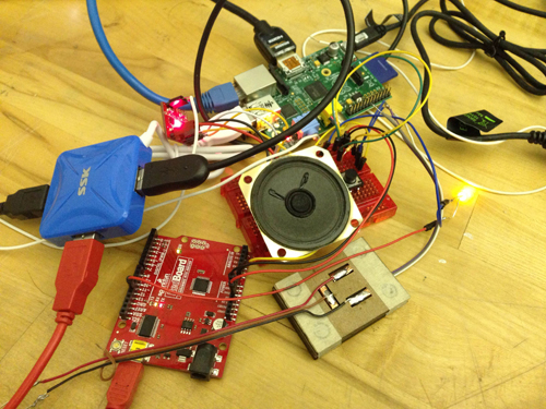
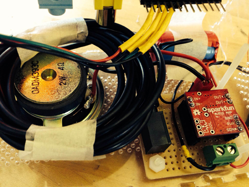
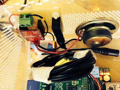
1. sound output amplification circuit. I first used a breadboard to test the audio output circuit using an amplifier connecting a speaker with a switch to augment the output sound and then  finished soldering a protoboard.

photo_2

photo_7 (2)

photo_8 (2)

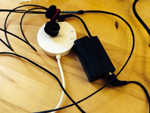
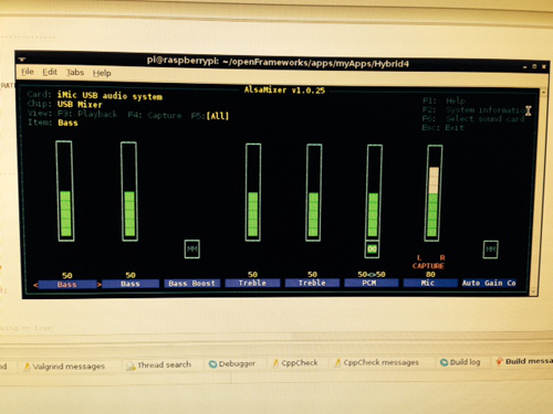
2. Sound capture device: a mic with a pre-amp connecting an usb audio card was used for sound input. However, it spent me a lot of  time to configure the parameters in the Raspberrry Pi to make it work. I referred to several blog posts in the website to get asoundrc and asound.conf file well set for audio card select and alsa mixer for control. A arecord and aplay command were used to test the recording in linux. Then I revised an addon of OF ofxLibsndFileRecorder to achieve recording. However, from the testing result, the system is not very robust, sometimes the audio input will fail and sometimes the play speed will much faster than recording speed, accompanying much noise.

photo_11照片2

alsamixer

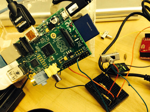
3. GPIO test: in order to test control the audio input and output with  switch and button. I first used a breadboard connecting a switch with a pull-up or pull down resister as the recording/play control.

photo_22

4. Case building: a transparent case using laser cut was built.

photo(1)

5. Simulink test: I searched that simulink recently supported the raspberry Pi with several well developed modules. So I tried to install an image of Simulink and run some simple demos with that platform. I also tested the GPIO control for triggering the switch between two sine wave generator in Simulink.

gpio1

Final Project Milestone 2 – Ziyun Peng

Assignment,Final Project — ziyunpeng @ 10:56 pm

My second milestone is to make a stable and ready to use system.

Mask
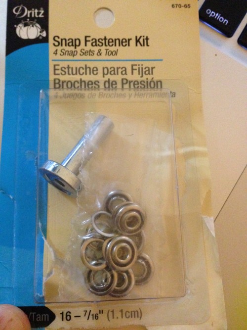
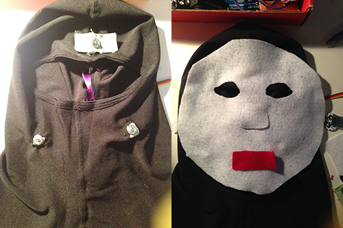
After several tries, I finally got to decide on where the sensing points should be on the face and replaced the electrodes with conductive fabrics following this tutorial by the sensor kit provider. It took me couple of amazon trips to find the right sized snap button and finally got the right ones from Lo Ann. The right size should be 7/16 inches (1.1cm) as is shown in the picture below, in case any of you would need it in the future.

2013-11-22 22.58.06

mask

Center Board
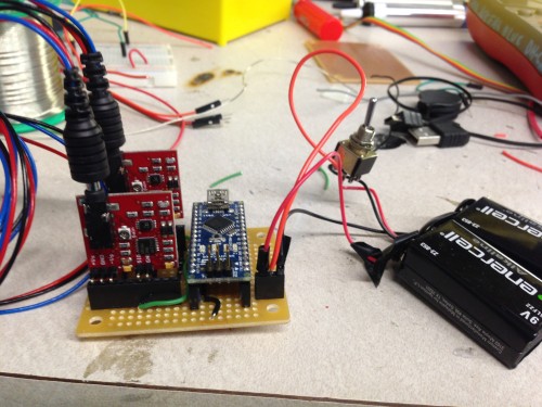
Since there won’t be any change in the circuit, it’s time to solder! What you can see on the board is two muscle sensor breakout, and Arduino Nano and two 9V batteries. The wires coming out will be connected to the buttons on the mask for getting data on the face.

2013-11-22 21.37.16

Final Project Milestone 2 – Mauricio Contreras

Assignment,Final Project,Robotics,Submission,Technique — mauricio.contreras @ 10:02 pm

Log

My second milestone was about simulating the motion of a robotic arm within the software workflow that had been explored in the first milestone (Rhino + Grasshopper + HAL). Upon getting acquainted with the capabilities of these pieces of softwares and understanding more about the possible constraints and needs of the instrument, I realized that REAL TIME driving of the robotic arm was a major requirement. Just imagine sculpting with your arm moving with a few seconds lag after your movement intention and you’ll see why. The software workflow described above is great for offline materialization of 3D designs, but not necessarily for real time control. Even though feasible, people from the lab commented about possible lag issues, which made me want to try out the real motion of the robot, even with simple commands, as soon as possible. I found procuring the tools to run in my own machine rather difficult: All of them are Windows only, so at first I got a virtual machine from Ali Momeni with everything preloaded, but it ran excruciatingly slow (even when I changed my computer to the latest Macbook Pro). Then I tried creating my own virtual machine from scratch, and installed Rhino and Grasshopper with success. Yet HAL’s developer webpage was down and I had problems procuring tutorial training for it. When I asked for help with this, people recommended to learn the former 2 tools first and then use HAL. This seemed reasonable but I was under time constraints (by choice) to test the robots motion as soon as possible with a configuration that would generate the least lag, and evaluate if that optimal setup would prove to be responsive enough to match the target application of the instrument, which is sculpting.

Early motion tests

I then turned to writing my own RAPID code, and quickly was able to generate a routine to move the head of the robot in a square in the air, as shown in the following video.

The routine was based on offsetting the current location by steps in each axis, but also waiting for a digital input state before each small step. Since the robot accepts 24 V digital inputs, I would have had to use a power source or do a conversion circuit from the standard micro controllers 5/3.3 V outputs. That is not difficult but I assumed that the DI of the robots had pull down resistors and just made it wait for DI=0 before each motion. Since the shape was completed that thesis was proven. Also, the motion seemed “cut”, as if doing start-pause-restart in every step, as opposed to a seamlessly continual motion that would have occurred either if the lag on processing the digital input was very low or depending on motion configuration of the robot (i.e. there may be other motion commands that would output less of a “cut” motion). I removed the wait for DI statements with no appreciable effect, hence the motion commands were the issue. To see the effect of this when driving the robot with gestures, and based on previous code for motion (FUTURE CNC LINK), I started writing a TCP/IP socket based client (Android smartphone) – server (robot controller) application, which will be outlined in the next milestone posting.

Assessment

Up to this milestone, just getting access to the robots themselves and being able to move them in a hardcoded fashion I consider a success by itself, yet it is clear that new, unforeseen difficulties have appeared.

Final Project Milestone 2 – Haochuan Liu

Assignment,Audio,Final Project — haochuan @ 7:37 pm

For my milestone 2, I have did a lot of experiments of audio effects in puredata. Besides very simple and common effects (gain, tremolo, distortion, delay, wah-wah) I made in milestone 1, here are the tests and demos I made for these new effects with my guitar.

Test 1: Jazz lead guitar

  • Original audio


  • Bass Synth


  • Falling Star


  • Phaser


  • Reverb


  • Ring Modulation


  • Slow Vibrato


  • Magic Delay


  • Violin


  • Vocoder


Test 2: Acoustic guitar

  • Original audio


  • Bass Synth


  • Falling Star


  • Phaser


  • Reverb


  • Ring Modulation


  • Slow Vibrato


  • Magic Delay


  • Violin


  • Vocoder


Test 3: Guitar single notes

  • Original audio


  • Bass Synth


  • Falling Star


  • Magic Delay


  • Vocoder


« Previous PageNext Page »
This work is licensed under a Creative Commons Attribution-Noncommercial-Share Alike 3.0 Unported License.
(c) 2024 Hybrid Instrument Building 2014 | powered by WordPress with Barecity