Final Project Milestone 2 – Ding Xu

Audio,Final Project,Laser Cutter,OpenCV — Ding Xu @ 11:05 pm

In my second milestone. I finished the following stuff:

1. sound output amplification circuit. I first used a breadboard to test the audio output circuit using an amplifier connecting a speaker with a switch to augment the output sound and then  finished soldering a protoboard.

photo_2

photo_7 (2)

photo_8 (2)

2. Sound capture device: a mic with a pre-amp connecting an usb audio card was used for sound input. However, it spent me a lot of  time to configure the parameters in the Raspberrry Pi to make it work. I referred to several blog posts in the website to get asoundrc and asound.conf file well set for audio card select and alsa mixer for control. A arecord and aplay command were used to test the recording in linux. Then I revised an addon of OF ofxLibsndFileRecorder to achieve recording. However, from the testing result, the system is not very robust, sometimes the audio input will fail and sometimes the play speed will much faster than recording speed, accompanying much noise.

photo_11照片2

alsamixer

3. GPIO test: in order to test control the audio input and output with  switch and button. I first used a breadboard connecting a switch with a pull-up or pull down resister as the recording/play control.

photo_22

4. Case building: a transparent case using laser cut was built.

photo(1)

5. Simulink test: I searched that simulink recently supported the raspberry Pi with several well developed modules. So I tried to install an image of Simulink and run some simple demos with that platform. I also tested the GPIO control for triggering the switch between two sine wave generator in Simulink.

gpio1

Final Project Milestone 2 – Haochuan Liu

Assignment,Audio,Final Project — haochuan @ 7:37 pm

For my milestone 2, I have did a lot of experiments of audio effects in puredata. Besides very simple and common effects (gain, tremolo, distortion, delay, wah-wah) I made in milestone 1, here are the tests and demos I made for these new effects with my guitar.

Test 1: Jazz lead guitar

  • Original audio


  • Bass Synth


  • Falling Star


  • Phaser


  • Reverb


  • Ring Modulation


  • Slow Vibrato


  • Magic Delay


  • Violin


  • Vocoder


Test 2: Acoustic guitar

  • Original audio


  • Bass Synth


  • Falling Star


  • Phaser


  • Reverb


  • Ring Modulation


  • Slow Vibrato


  • Magic Delay


  • Violin


  • Vocoder


Test 3: Guitar single notes

  • Original audio


  • Bass Synth


  • Falling Star


  • Magic Delay


  • Vocoder


Final Project Presentation: Liang

Final Project,Laser Cutter,Sensors — lianghe @ 2:52 am

The final project goes wrong with Pin conflict on Trinket. Since I use Pin #1 to read microphone’s digital data and Pin #2 (Trinket requires “1”, which means A1, instead of “2” in code) to read analog X-axis accelerometer data,  it gets confused when I have to write the same command “PinMode(1, INPUT);” in the code to execute both data read. It leads to the failure of reading microphone and accelerometer at the same time. Annoyingly, I had to use Teensy at the very last minute instead to perform my demo. It was not robust and that good, and very preliminary. I felt sorry for the audience and reviewers that night. However, they gave me a lot of feedback and suggestions on potential revise and development. Here I sum up some key points:

1. My biggest problem is that I attempt to cover many scenarios and applications, which is so generic that confuses audiences and eventually lose its value. It fails to address the major problem it tries to figure out, or the goal for its exist. It throws abstract pictures to audience, leave alone under the situation that it cannot work.

2. The gesture seems weird since the microphone works part the role of the gesture. I would argue that the gesture is kind of the way people feel the liquid in the cup. Honestly, when I design the gesture, I find only one gesture (shake) is meaningful for people.

3. Other formations. No matter what kind of stuff I want to create and make, it should respect my motivation and its goal. So, again it goes back to “Point #1”.

I agree with most of the comments in the critique and they drive me recall my original motivation: I know cup has resonance with liquid, cup has material, people use cup, and it can be an instrument to perform music. In the past weeks, I continue to do some research how to make use of these characters and what kind of music it can generate. Here I have some answers: it can generate beats, then rhythm, so it can perform some kind of percussion performance. Besides cups, other objects also have resonance property. When I look back at these, I narrow down my scenario for Tapo and come up with a new but iterative design and development solution.

Redefine the story for TAPO

Physical objects have resonance property and specific material. Tap object gives different sound feedback and percussion experience. People are used to making rhythms by beating objects. So, why not provide a tangible way not only allowing people to make rhythms with physical objects around she/he, but also enriching the experience by some computational methods. The ultimate goal for this project is that ordinary people can make and play rhythms with everyday objects, even perform a piece of percussion performance.

Final Project Milestone 2 – Robert Kotcher, Haris Usmani

Assignment,Description,Hardware,Uncategorized — rkotcher @ 10:44 am

Milestone 1,2 Goals:

Milestone 1: Explore different types of actuators, and the sounds they can produce in different spaces. Determine how we can enhance these sounds in Pure Data.

Milestone 2: Make CAD models for crickets, build proof-of-concepts, and order any additional parts we might need.

Milestone 2 Progress:

The implementation of our milestone 2 goals was carried out in two separate areas. The first involved creating a box that could hold the components necessary for a cricket, and the second part was getting the Udoo to talk to a single actuator. Each of these items are described in detail below, and progress photos are also listed throughout the rest of this post.

Hardware Design of Crickets:
We decided to make a laser cut box to hold all our electronics, and to support the ‘goose-necks’ we plan to use to position and hold the actuators in place along with providing us flexibility. This box is now designed and we have a 2nd prototype of it- there are three compartments: The 1st compartment holds the Udoo, the 2nd houses the 50W x 2 Audio Amp and the 3rd holds the battery and the power/driving circuitry.

The box is strong enough to hold the weight of the goose-necks and the actuators. All sides are ‘interlocking’ except for one. This side allows service of inner electronics, as required.

The top and bottom of the box are cut with a thicker sheet of Masonite, as these would support the box or the actuators. So the plan is to allow this box to be attached to any 1/4 inch 20 bolt holder (like all tripods) so it can attach to whatever support we want. To distribute the weight, we will thread a 1/4 inch 20 into a metal sheer (similar to the template you can see in the diagram) and cut it so as to bind it to the lower side of the box. The top of the box already has space for attaching 4 actuators, as the four holed allow 4 goose-necks to be attached- we wouldn’t use more than 2 for now.

All the hardware required (screws, bolts, nuts) have been ordered.

IMG_0343

Udoo, actuators
Our initial tests with the actuators used simple transistors connected directly to a DC power supply. This week we were able to connect a striker to the Udoo, and control it using a simple PureData software interface to the Udoo’s GPIOs.

Specifically, our striker actuator is connected to a DRV8835 dual motor driver, which uses logical power from the Udoo, and motor power from a battery back. We’ll need two of these motor drivers for each cricket, each of which will control four actuators.

The video below shows our basic setup. The next step is to make the circuitry more robust and portable, so that we can quickly scale to more actuators in week 3.

IMG_0340

Final Project Milestone One: Jake Berntsen

My struggles thus far in this class have rested almost entirely on the physical side of things; I’m relatively keen with regards to using relevant software, but my ability to actually build devices is much less developed, to say the least.  With this in mind, I decided to make my early milestones for my final project focus entirely on the most technically challenging aspects in terms of electrical engineering; specific to my project, this meant getting all of the analog sensors running into my Teensy to obtain data I could manipulate in Max.  To do so meant a lot of prototyping on a breadboard.

IMG_1449

After exploring a wide variety of sensors, I found a few that seemed to give me a sharp control of the data received by Max.  One of my goals for this project is to create a controller that offers a more nuanced musical command than the current status quo, and I believe that the secret to this lies within more sensitive sensors.


The sensors I chose are picture below: Joysticks, Distance Sensors, Light Sensors, and a Trackpad.

Joystick


Light Sensor


IMG_1445


IMG_1447


All of the shown sensors have proven to work dependably, with the exception of some confusion regarding the input sensors of the trackpad.  The trackpad I am using is from the Nintendo DS gaming device, and while it’s relatively simple to get data into Arduino, I’m having trouble getting data all the way into Max.

The other hardware challenge that I was facing this week was fixing the MPK Mini device that I planned to incorporate into my controller.  The problem with it was a completely detached mini USB port that is essential to the usage of the controller.  Connecting a new port to the board is a relatively simple soldering job, and I successfully completed this task despite my lack of experience with solder.  However, connecting the five pins that are essential for getting data from the USB is a much more complicated task, and after failing multiple times, I decided to train myself a bit in soldering before continuing.  I’ve not yet seen success, but I’ve improved greatly in the past few days alone and feel confident that I will have the device working within the week.

IMG_1451

IMG_1450


If I continue working at this rate, I do believe that I will finish my project as scheduled.  While I was anticipating only being able to use the sensors that I could figure out how to use, I instead was able to make most of the ones I tried work with ease and truly choose the best one.

IMG_1452

Final Project Milestone 1 – Ding Xu

We live in a world surrounding by different environments. Since music could have mutual influence with human’s emotions, environments also embrace some parameters which could get involved in that process. In certain content, environment may be a good indicator to generate certain “mood” to transfer into music and affect people’s emotions. Basically, the purpose of this project is to build a portable music player box which could sense the surrounding environment and generate some specific songs to users.

This device has two modes: the search mode and generate mode. In the first mode, input data will be transformed into some specific tags according to its type and value; then these tags are used to described a series of existing songs to users. In the second mode, two cameras are used to capture ambien images to create a piece of generative music. I will finish the second mode in this class.

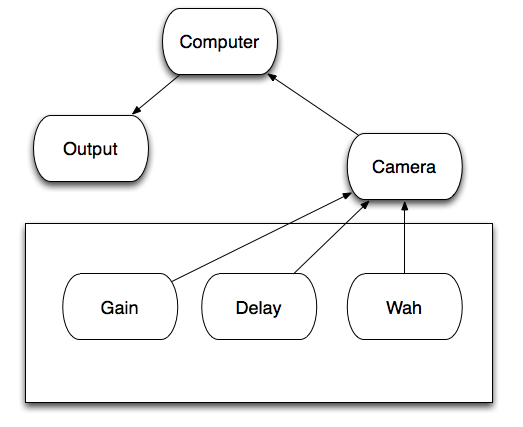
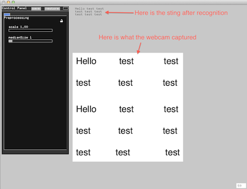
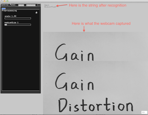
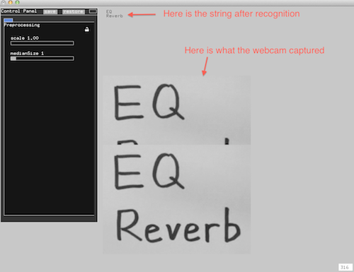
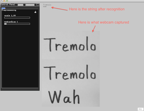
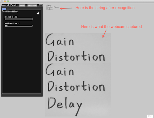
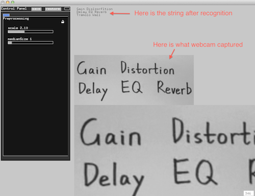
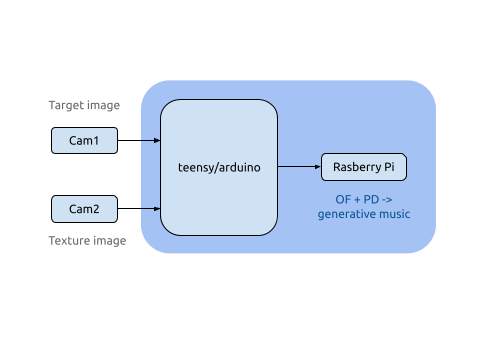
In mode 2, for each piece of song, two types of images will be used. The first one is a music image captured by an adjustable camera and the content of this image will be divided into several blocks according to their edge pixels and generate several notes according to their color. The second image is a texture one captured by a camera with a pocket microscope. When the device is placed on the different materials, corresponding texture will be distinguished and attach different instrument filter to music.

Below is a list of things I finished in the first week:

  • System design
  • platform test and select specific hardware and software for project
  • Be familiar with raspberry pi OS and Openframeworks
  • Experiment about data transmission among gadgets
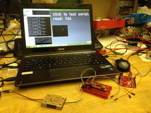
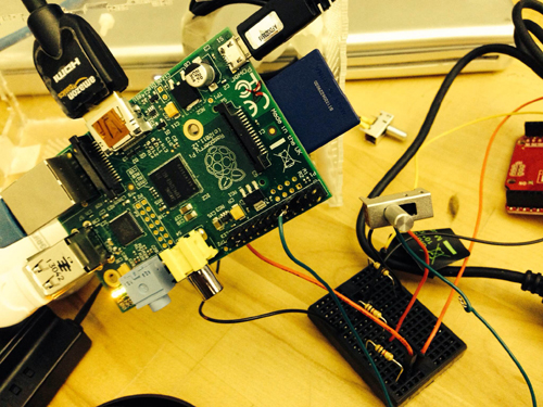
  • Serial communication between arduino/teensy and Openframeworks
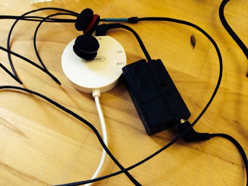
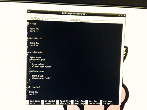
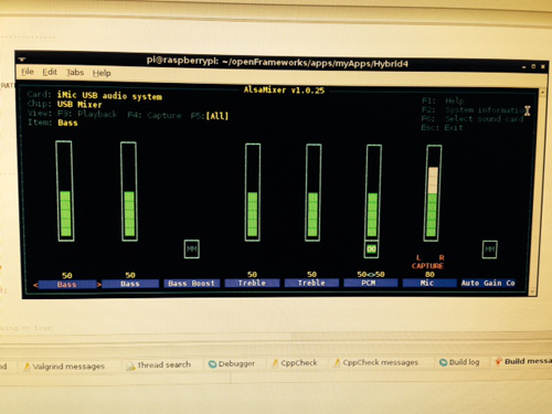
  • get a video from camera and play sound in openframeworks

Platform test:

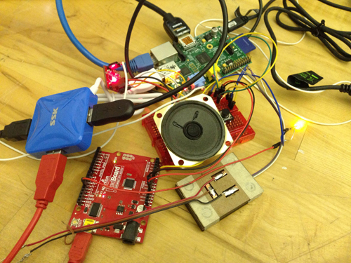
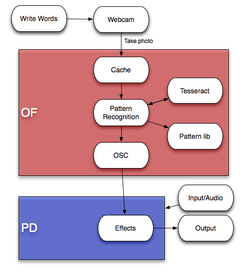
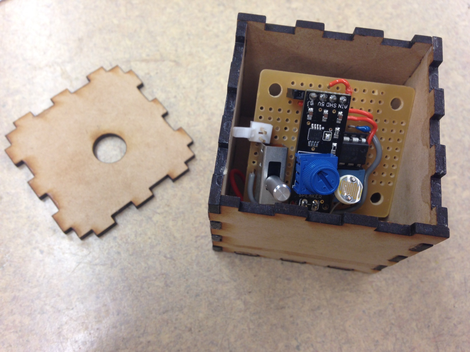
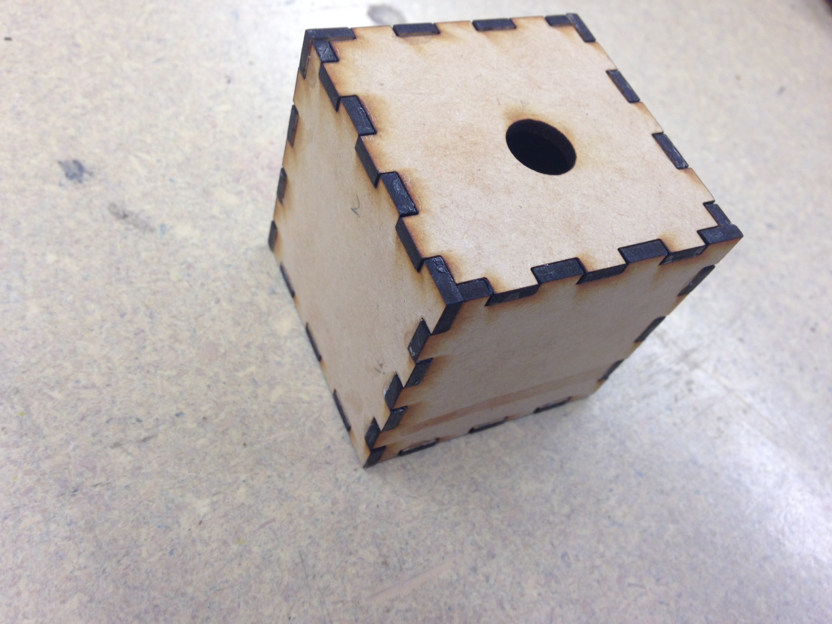
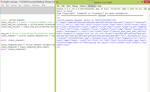
Since this device is a portable box which need to be played without supporting of a PC,  therefore, I want to use raspberry pi, arduino and sensors (including camera and data sensors) to do this project. As for the software platform, I chose openframeworks as the maor IDE and plan to use PD to generate sound notes, connecting it with openframeworks for control. Moreover, it’s more comfortable for me to use C++ rather than python, since I spent much more time to achieve some a HTTP request to log into Jing.FM in python.

Python test

Raspberry Pi Network setting

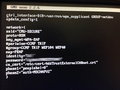
As a fresh hand for Raspberry Pi without any knowledge about Linux, I got some problems when accessing into the CMU-secure wifi with Pi since the majority of tutorial is about how to connect the Pi with a router, and CMU-secure is not the case. Finally, I figured it out with the help of a website explaining the very specific parameters in wpa_supplicant.conf, the information provided by CMU computing service website and copying the certificate file into Pi. I also want to mention that each hardware which use CMU wifi need to register the machine in netreg.net.cmu.edu/ and this process takes effect after 30 minutes.

Raspberri Pi

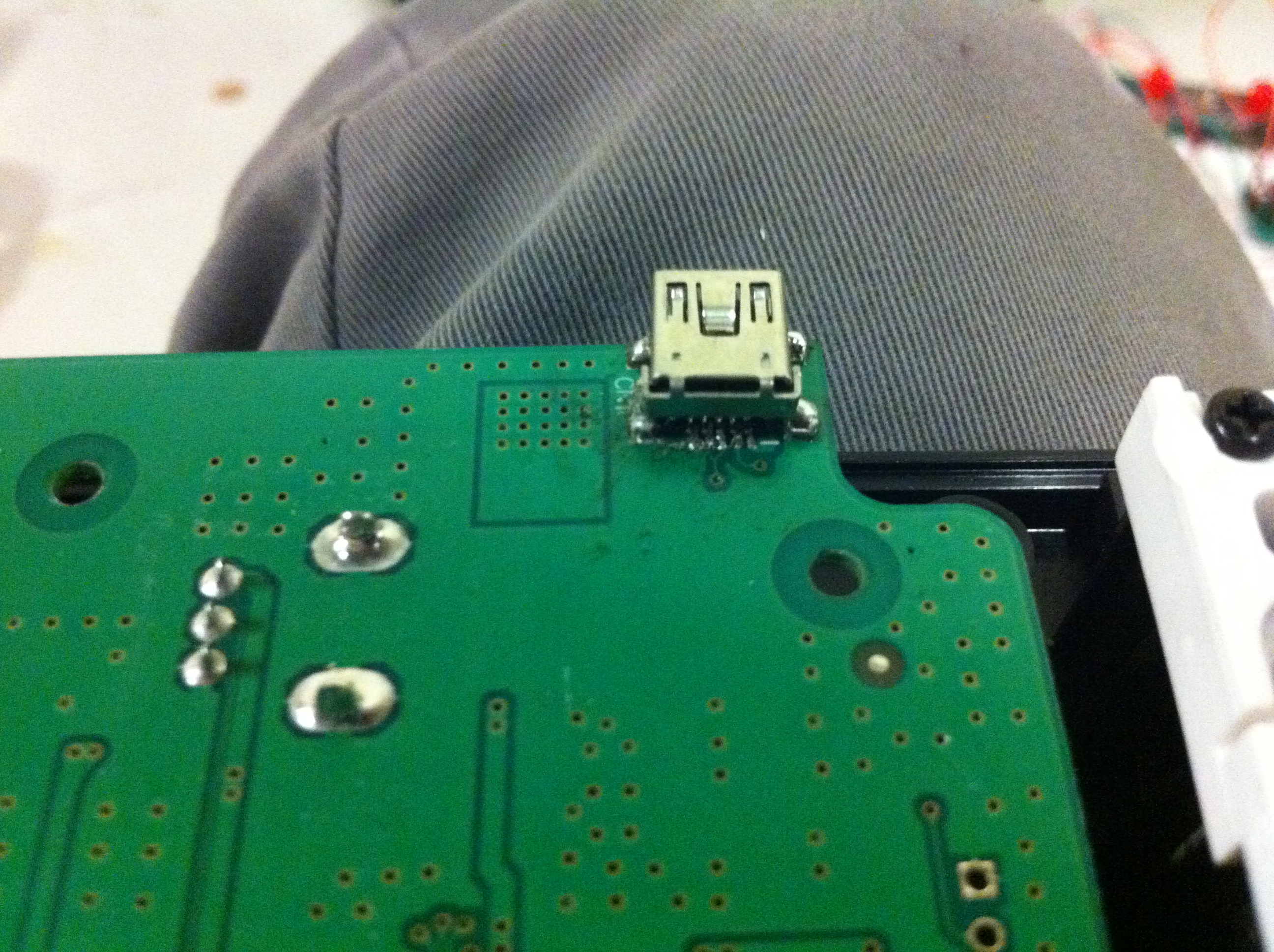
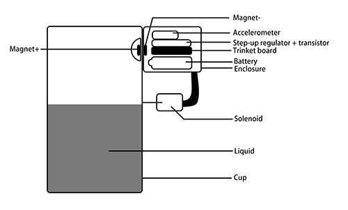
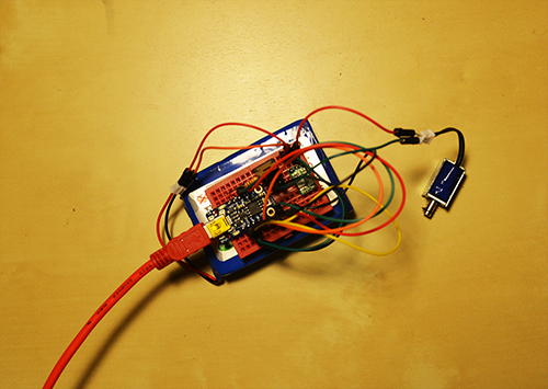
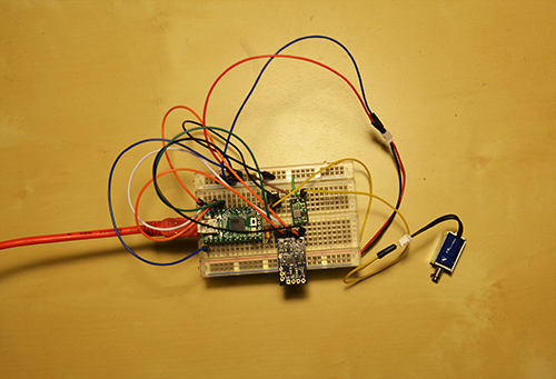
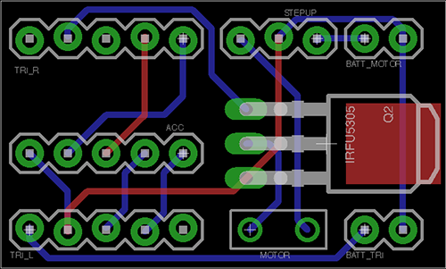
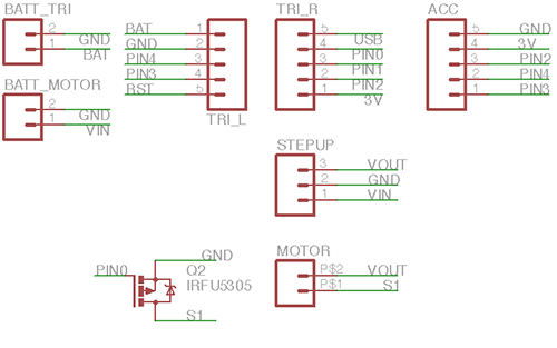
Data Transmission between gadget and arduino

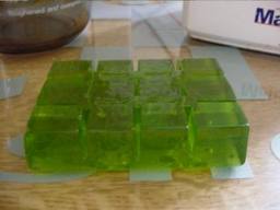
Experiment 1: Two small magnets attached in the gadget with the height of 4 mm

gadget1

gadget

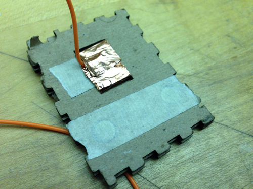
Experiment 2: Four magnets attached in the gadget with the height of  2.9 mm and 3.7 mm

gadget2


gadget3

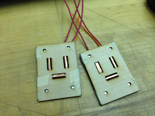
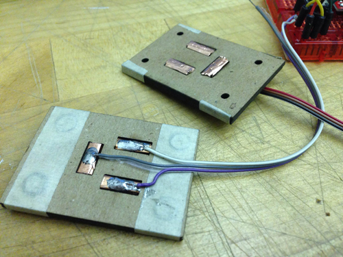
the prototype 2 is easier to attach the gadgets together but all of these gadgets fail to transmit accurate data if not pressing the two their sides. A new structure is required to build to solve this problem.

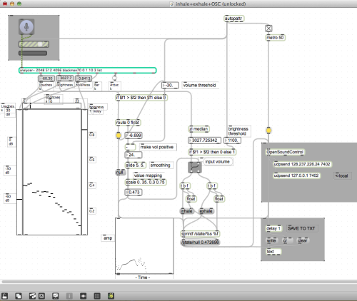
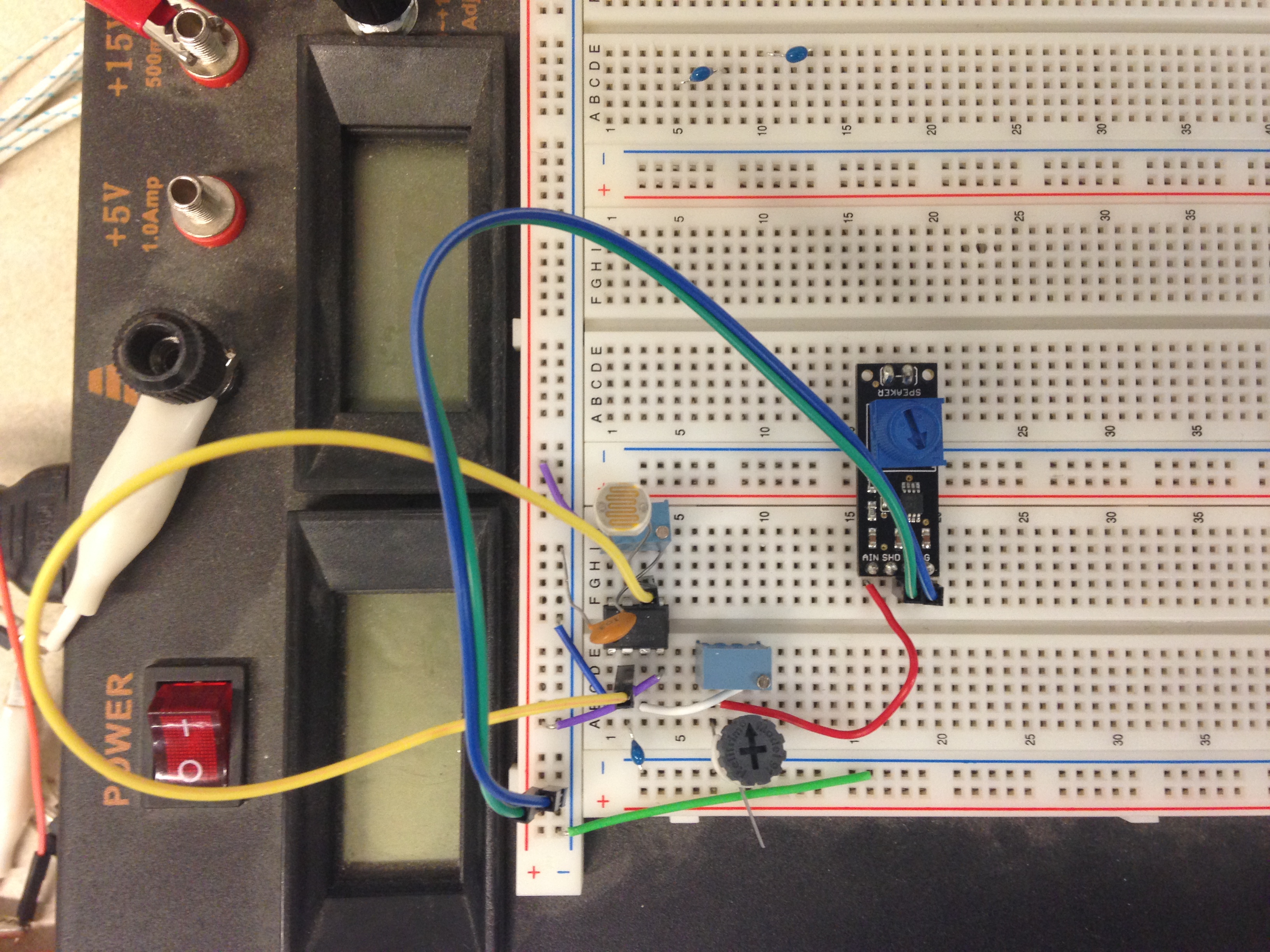
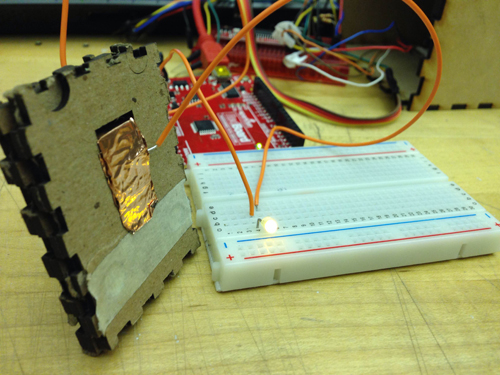
Connecting arduino with openframeworks with serial communication

Mapping 2 music to different sensor input data value

OF test2

Final Project Milestone 1 – Ziyun Peng

Assignment,Final Project,Max,Sensors — ziyunpeng @ 10:45 am

My first milestone is to test out the sensors I’m interested in using.

Breath Sensor: for now I’m still unable to find any off-the-shelf one which can differentiate between inhale and exhale. Hence I went to the approach using homemade microphone to get audio and using Tristan Jehan‘s analyzer object with which I found the main difference of exhale and inhale is the brightness. Nice thing about using microphone is that I can also easily get the amplitude of the breath which is indicating the velocity of the breath.  Problem with this method is it needs threshold calibration each time you change the environment and homemade mic seems to be moody – unstable performance with battery..

mini-mic

breath

Breath Sensor from kaikai on Vimeo.

Muscle Sensor:  It works great on bicep although I don’t have big ones but the readings on face is subtle – it’s only effective for big facial expressions – face yoga worked. It also works for smiling, opening mouth, and also frowning (if you place the electrodes just right). During the experimentation, I figure it’s not quite a comfortable experience having sticky electrodes on your face but alternatives like stretching fabric + conductive fabric could possibly solve the problem which is my next step. Also, readings don’t really differentiate each other, meaning you won’t know if it’s opening mouth or smiling by just looking at the single reading. Either more collecting points need to be added, or it could be coupled with faceOSC which I think is more likely the way I’m going to approach.

EMG_faces

FaceOSC: I recorded several facial expressions and compared the value arrays. The results show that the mouth width, jaw and nostrils turned out to be the most reactive variables. It doesn’t perform very well with the face yoga faces but it does better job on differentiating expressions since it offers you more parameters to take reference of.

faceOSC_faces

Next step for me is to keep playing around with the sensors, try to figure out a more stable sensor solution (organic combination use) and put them together into one compact system.

Final Project Milestone 1 – Haochuan Liu

Assignment,Audio,Final Project,OpenCV — haochuan @ 10:28 am

Plan for milestone 1

The plan for milestone 1 is to build the basic system of the drawable stompbox. First, letting the webcam to capture the image of what you have drawn on paper, then the computer can recognize the words on the image. After making a pattern comparison, the openframwork will send a message to puredata via OSC. Puredata will find the right effect which is pre-written in it and add it to your audio/live input.


milestone 1 plan


Here is the technical details of this system:

Screen Shot 2013-10-30 at 4.53.23 PM

After writing words on a white paper, the webcam will take a picture of it and then store this photo to cache. The program in OpenFrameworks will load the photo, and turn the word on the photo to a string and store it in the program using optical character recognition via Tesseract. The string will be compared to the Pattern library to see if the stompbox you draw is in the library. If it is, then the program will send a message to let PureData enable this effect via OSC addon. You can use both audio files or live input in puredata, and puredata will add the effect what you have drawn to your sound.

Here are some OCR tests in OF:

test1-result test2-result test3-result test4-result test5-result test6-result


About the pattern library on OF:

After a number of test for OCR, the accuracy is pretty high but not perfect. Thus a pattern library is needed to do a better recognition. For example, Tesseract always can not distinguish “i” and “l”, “t” and “f” , and “t” and “l”. So the library will determine what you’ve drawn is “Distortion” when the result after recognition is “Dlstrotlon”, “Disforfion” or “Dislorlion”.

Effects in PureData:

Until now, I’ve made five simple effects in PureData, which are Boost, Tremolo, Delay, Wah, and Distortion.

Here is a video demo of what I’ve done for this project:

Hybrid Instrument Final Project Milestone 1 from Haochuan Liu on Vimeo.


Final Project Milestone #1: Liang

Assignment,Final Project,Hardware,Sensors — lianghe @ 5:21 am

Project: Tapo

Tapo is a tangible device encouraging people to create beats and perform percussion music with daily cups. What kind of beats it can produce? The volume of the liquid in the cup, the material of the cup and how people interact with the cup matter. The pitch and the timbre depend on the resonant property and the material of the cup. People’s gesture decides the speed or the pattern of the beat.

In the past one and a half week I accomplished every items listed for my first milestone.

1. System Design: I sketched the whole system design and labeled every component in the sketch.

system


2. Basic Diagram: Based on the system design, I finished the system diagram.

3. Quick Prototype: I have finished two prototypes so far. One is composed of a Trinket, a 1K resistor, a step-up regulator, a transistor (TIP 120), an accelerometer, a solenoid and a battery. The other one is different from this one by using a Teensy and a smaller transistor (FU3910) instead. These two prototypes are currently supported by a big battery set and USB power supply. In the final version I will replace by two separate batteries supporting the micro controller and the solenoid, also use all the tiny components in one enclosure. The Trinket version almost has the final look of this project except for the transistor and the batteries. However, the cheap board Trinket does support the Serial debug. Therefore, I built the second prototype by Teensy for the next phase: gesture’s detection with accelerometer.

milestone_pic1

Prototype 1

milestone_2

Prototype 2

The prototype 1 is implemented to test the solenoid and the prototype 2 combines solenoid and accelerometer, which converts the data of accelerometer into the speed of the solenoid. Both prototypes are testified that solenoid, accelerometer and the entire hardware configuration can work.

4. Circuit Design: In order to produce multiple devices, I customised a PCB board for all the hardware components, including batteries ports, solenoid interface, transistor, resistor, step-up regulator, and accelerometer.

PCB_final PCB_Schematics


5. Component Purchase: I did a research on every component I would use in this project and test several transistors and boards, listed a budget for the hardware that I need. I have all the parts at hand for just one prototype. Here is some links of my wanted components:

Trinket: www.adafruit.com/products/1500

Batteries: www.amazon.com/gp/product/B006N2CQSS/ref=oh_details_o00_s00_i00?ie=UTF8&psc=1

www.adafruit.com/products/1570

Solenoid: https://www.sparkfun.com/products/11015

Final Project Milestone #1—Wanfang Diao

Assignment,Audio,Final Project,Hardware — Wanfang Diao @ 12:26 am


My first milestone is :” Build circuits to make sounds first and then try to the recognition part”.

In the first two week, I tried the circuits to make sound at certain pitch. The circuit I use is the 555 timer circuits, by changing the resistor, the frequency of the signal of out put can be changed.

tim47


After building the below circuits successfully on bread board, the sound is not perfect, I add a low pass filter but it helps little. So I plan to solve this problem by mechanical way.


2013-10-28 21.09.39 2


I soldering the circuits on proto board and add photo sensor and a switch. The photo sensor is in order to support the idea that by changing the cube’s up-face to change cube mode (i.e. # b ). As show in the video below, I also try to use different material covering on the speaker to get better audio effect. I’ll also keep trying other kinds of circuits to solve this.


About battery: the size of battery will limits my cubes size, so I plan to use use this one: www.sparkfun.com/products/341


2013-10-28 21.17.07 from Wanfang Diao on Vimeo.

Material

I have laser cut a wooden cube which is 5.5cm*5.5cm*5.5cm, but I feel the material is not cute enough.

__ 2

__ 1

__ (1)

So I plan to try more flexible materiel like image below which is silicone. I want the cube to feel like jelly.


I also realize that before I design the mother mold for silicone cube I have to decide the final electronic part design.


IMG_2491

images


« Previous PageNext Page »
This work is licensed under a Creative Commons Attribution-Noncommercial-Share Alike 3.0 Unported License.
(c) 2024 Hybrid Instrument Building 2014 | powered by WordPress with Barecity