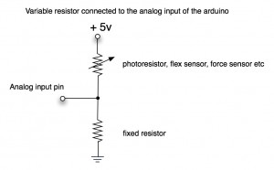
We continue our work with sensing circuits (using photoresistors) and actuators (LEDs, incandescent light bulbs, motors, and servos). Connect the necessary components on a bread-board to do the following:
- One photo resistor controlling the rotation of a servo motor
- One photo resistor controlling the brightness of an LED
- One photo resistor controlling the brightness of an incandescent light bulb
- One photo resistor controlling the speed of a DC motor
Once the circuitry and the Max patch for the above set of mappings is complete, the begin integrating elements from your collection of very-small-things, by attaching some of your collected items to your motors and servos, and lighting other collected items with LEDs and light bulbs
Simple circuit for connecting a variable resistance sensor to a micro-controller (with details regarding our favorite microcontroller the Arduino-compatible Teensy):


The above diagram shows how to use a microcontoller (like our Arduino-compatible Teeny board) and a MOSFET to turn on/off a DC motor or a light.
In the above diagram:
- “Load”: your light or actuator (including motors, solenoids) and its two leads
- “Load Power +12″: the positive terminal of your power supply; note that this voltage can be different than +12V” as long its within the MOSFET’s specifications
- “MOSFET”: the three leads are labeled [G]ate, [D]rain and [S]ource; refer to the MOSFET’s datasheet to assure which pin is which
- Grounds: the MOSFET’s [S]ource pin connects to the ground of the power supply; the microcontroller’s ground pin should also be connected to the ground of the power supply
- “Control +5V”: this connection is to one of the digital outputs pins of the microcontroller (either Digital I/O or PWM)

