Final Project Documentation: The Wobble Box

Assignment,Audio,Final Project,Laser Cutter,Max,Sensors — Tags: , , , — Jake Berntsen @ 5:16 pm

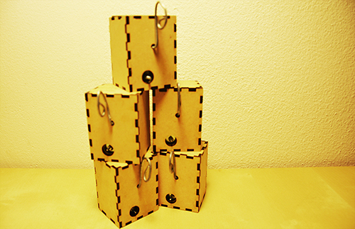
After taking time to consider exactly what I hope to accomplish with my device, the aim of of my project has somewhat shifted. Rather than attempt to build a sound-controller of some kind that includes everything I like about current models while implementing a few improvements, I’ve decided to focus only on the improvements I’d like to see. Specifically, the improvements I’ve been striving for are simplicity and interesting sensors, so I’ve been spending all of my time trying to make small devices with very specific intentions. My first success has been the creation of what I’m calling the “Wobble Box.”

IMG_1522

IMG_1524

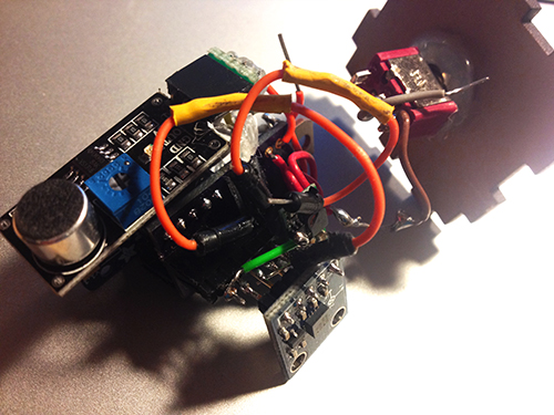
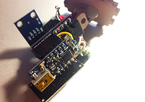
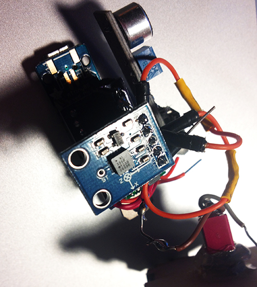
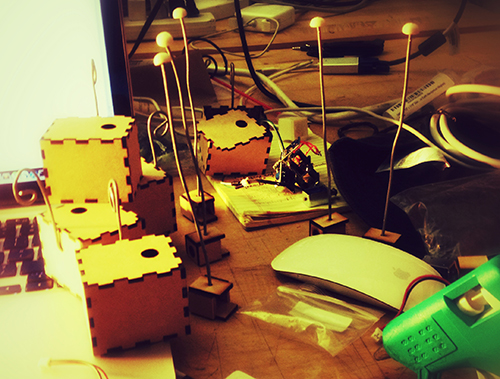
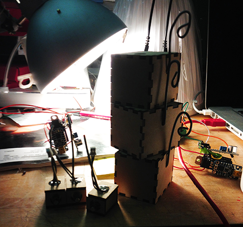
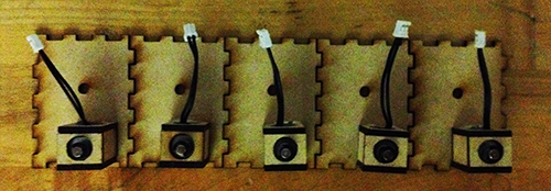
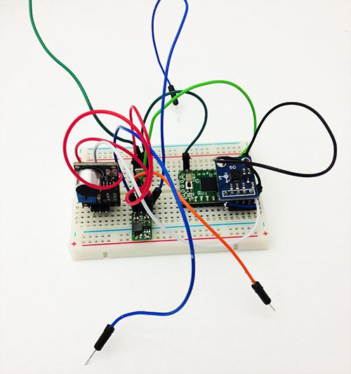
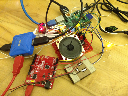
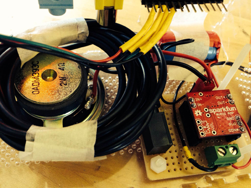
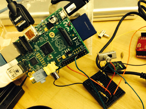
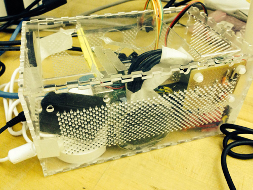
Simply stated, the box contains two distance sensors which are each plugged into a Teensy 2.0.  I receive data from the sensors within Max, where I scale it and “normalize” it to remove peaks, making it more friendly to sound modulation.  While running Max, I can open Ableton Live and map certain audio effects to parameters in Max.  Using this technique I assigned the distance from the box to the cutoff of a low-pass filter, as well as a slight frequency modulation and resonance shift.  These are the core elements of the traditional Jamaican/Dubstep sound of a “wobble bass,” hence the name of the box.  While I chose this particular sound, the data from the sensors can be used to control any parameters within Ableton.

IMG_1536

IMG_1535

IMG_1532

Designing this box was a challenge for me because of my limited experience with hardware; soldering the distance sensors to the board was difficult to say the least, and operating a laser-cutter was a first for me.  However, it forced me to learn a lot about the basics of electronics and I now feel confident in my ability to design a better prototype that is smaller, sleeker, and more compatible with similar devices.  I’ve already begun working on a similar box with joysticks, and a third with light sensors.  I plan to make the boxes connectible with magnets.

IMG_1528For my presentation in class, I will be using my device as well as a standard Akai APC40.  The wobble box is not capable or meant to produce its own melodies, but rather change effects on existing melodies.  Because of this, I will be using a live-clip launching method to perform with it, making a secondary piece of hardware necessary.


Final Project Milestone #3: Liang

Final Project,Laser Cutter,Rhino3D,Sensors — lianghe @ 2:23 am

1. My boards arrived!!

After about 12 days, OSH Park fabricated and delivered my boards. Yes, they are fantastic purple and look like exactly what I expect. I soldered and assembled every components together to test the board. Finally, all boards work with all the components but the transistor. I used smaller one instead of TIP 120. For some reason, it could work with Trinket board. So, I used TIP 120 again with my final board.

photo


2. Add Microphone Module!

To solve the problem of gestures and how user interacts with cup and Tapo, I decided to use a microphone to record user’s input (oral rhythm, voice, and even speech). The idea is quite simple: since the electret microphone turns analog voice data into digital signal, I can just make use of the received signal and generate certain beat for a rhythm. That is more reasonable interaction for users and my gestures can be put into two categories: trigger the recording and clear the recorded rhythm. The image below shows the final look of the hardware part, including the PCB board, Trinket board, transistor, step-up voltage regulator, solenoid, accelerometer, electret microphone, and a switch.

photo

photo1


photo2


3. Fabrication!

All parts should be enclosed in a little case. At the beginning I was thinking of 3D printing a case and using magnets to fix the case on the cup. I 3D printed some buckets with magnet to see the magnetic power. It seemed not very well in attracting the whole case. The other thing looks difficult for 3D printing case was that it was not easy to put the entire hardware part in and get it out.

photo copy

Then I focused on laser cutting.  I created a box for each unit and drilled one hole for solenoid, one hole for microphone and a hole for hook. I experienced three versions: the first one left one hole for the wire of solenoid to go through, thereby connecting with the main board. But the solenoid could not be fixed quite well (I used strong steel wire to support it); The second version put the solenoid inside the box and opened a hole on the back facet, so that it could tap the cup it was mounted on, but the thickness of the box avoided the solenoid to touch object outside; In the final version I drilled a hole on the upper plate for the switch, and modified the construction for solenoid.

photo

photo copy


Version 1

photo copy

Version 2

photo copy

Solenoids

DSC_0110 copy1

Version 3

Another thing is the hook. I started with a thick and strong steel wire and resulted in that it could not be bended easily. Then I used a thinner and softer one, so that it could be bended to any shape as the user wished.

photo copy

4. Mesh up codes and test!!

Before program the final unit, I programmed and tested every part individually. The accelerometer and the gestures worked very well, the solenoid worked correctly, and I could record user’s voice by microphone and transferred it to certain pattern of beats. Then the challenge is how to make a right logic for all the things work together.  After several days’ programming, testing, debugging, I meshed up all logics together. The first problem I met was the configuration of Trinket, which led to my code could not be burned to the board. Then the sequence of different module messed up. Since the micro controller processed data and events in a serial sequence, so the gesture data could not be “timely” obtained while the beats of solenoid depended on several delays.

I built a similar circuit, in which my custom PCB was replaced by a breadboard, to test my code. In the test, I hoped to check if my parameters for the interval of every piece of rhythm was proper, if the data number of the gesture set was enough to recognise gestures, if specific operation causes specific events, and most importantly, if the result looked good and reasonable.

Here is the test unit:

photo copy

Here is a short video demo of the test:

Final Project Milestone 2 – Ding Xu

Audio,Final Project,Laser Cutter,OpenCV — Ding Xu @ 11:05 pm

In my second milestone. I finished the following stuff:

1. sound output amplification circuit. I first used a breadboard to test the audio output circuit using an amplifier connecting a speaker with a switch to augment the output sound and then  finished soldering a protoboard.

photo_2

photo_7 (2)

photo_8 (2)

2. Sound capture device: a mic with a pre-amp connecting an usb audio card was used for sound input. However, it spent me a lot of  time to configure the parameters in the Raspberrry Pi to make it work. I referred to several blog posts in the website to get asoundrc and asound.conf file well set for audio card select and alsa mixer for control. A arecord and aplay command were used to test the recording in linux. Then I revised an addon of OF ofxLibsndFileRecorder to achieve recording. However, from the testing result, the system is not very robust, sometimes the audio input will fail and sometimes the play speed will much faster than recording speed, accompanying much noise.

photo_11照片2

alsamixer

3. GPIO test: in order to test control the audio input and output with  switch and button. I first used a breadboard connecting a switch with a pull-up or pull down resister as the recording/play control.

photo_22

4. Case building: a transparent case using laser cut was built.

photo(1)

5. Simulink test: I searched that simulink recently supported the raspberry Pi with several well developed modules. So I tried to install an image of Simulink and run some simple demos with that platform. I also tested the GPIO control for triggering the switch between two sine wave generator in Simulink.

gpio1

Final Project Presentation–Wanfang Diao

Arduino,Assignment,Final Project — Wanfang Diao @ 5:04 pm


More demos:

Note cubes from Wanfang Diao on Vimeo.

Note Cubes from Wanfang Diao on Vimeo.

Final Project Milestone 3 – Spencer Barton

3D Printer,Final Project,Instrument,Rhino3D,Scanning — spencer barton @ 8:47 pm

Model Making

I have begun to create models. The current models utilize additive methods: one with plaster printing (thanks to dFab) and PLA printing with a Makerbot in Codelab. I also utilized the Art Fab CNC to make a slightly larger rolly polly. Some of the below models are shown with the original object that I used for the capture.

2013-11-17 17.53.01

2013-11-17 18.06.09

2013-11-17 17.55.04

2013-11-17 18.08.14

2013-11-23 13.54.47

2013-11-23 13.54.20

2013-11-18 22.59.09

Final Project Milestone 2 – Jake Marsico

Assignment,Final Project,Max,Uncategorized — jmarsico @ 1:21 pm

_MG_2036

The Shoot

This past weekend I finished the video shoot with The Moon Baby. Over the course of three and a half hours, we shot over 80 clips. A key part of the project was to build a portrait rig that would allow the subject to register her face at the beginning of every clip. The first prototype of this rig consisted of a two way mirror that had registration marks on it. The mirror prototype proved to be inaccurate.

The second prototype, which we used for the shoot, relied on a direct video feed from the video camera, a projector and a projection surface with a hole cut out for the camera to look through.


At the center of this rig was a max/msp/jitter patch that overlayed a live feed from the video camera on top of a still “register image”. This way, the subject was able to see her face as the camera saw it, and line up her eyes, nose, mouth and makeup with a constant still image. See an image of the patch below:

max_screenshot


The patch relied on Blair Neal’s Canon2Syphon application, which pulls video from the Canon dslr’s usb cable and places it into a syphon stream.  That stream is then picked up by the max/msp/jitter patch.

Here is a diagram of the entire projection rig:

Woo portrait setup

Soon into the shoot, we realized a flaw with the system: the Canon camera isn’t able to record video to its CF card while its video feed is being sent to the computer.  As a result, we had to unplug the camera after the subject registered her face, record the clip, then plug the camera back in.  We also had to close and reopen Canon2Syphon after each clip was recorded.

SONY DSC

Wide shot of the entire setup.


To light the subject, I used a combination of DMX-controlled fluorescent and LED lights along with several flags, reflectors and diffusers.


Final Project Milestone 2 – Spencer Barton

Final Project,Rhino3D,Scanning — spencer barton @ 12:34 am

A Walk in the Woods

In the first milestone I defined five options for objects to capture. I decided to go with ‘A Walk in the Woods’:

I grew up playing in the woods. It was always an adventure – new bugs lay under every rock and dirt could be molded into innumerable forts. I have gradually left the woods behind (as I imagine most of us are doing these days). My goal is to take a simple walk through the woods and record any and all interesting discoveries that I make. These critters, rocks and leaves would then be created as physical models to capture some of that excitement of discovery.

Captures and Lessons Learned

I have performed a number of captures now, some with great success and others with less.

I have a few pointers for capture:

  • Lighting if important. Diffused light works better then a spotlight. Captures did well with just the microscope light on.
  • The angle of capture cannot be too deep. The objects did best at 30-45 degrees.
  • The object surroundings are very important as background objects help the software orient the images. Latter models all have orange clay bases for support and textured background.
  • 30x magnification worked well for the objects that I had. Captures work best when the capture can see a wide range of the object’s surroundings
  • Taking pictures at different focus depths came out well.
  • The more pictures the better. I usually took 40-70.
  • Shiny objects don’t do as well
  • Small details like bug legs are rarely captured.

Here are some of the results (all models available on my 123D account):

Future Steps

The next hurdle is manufacturing. I am exploring two options. One in 3D printing in plaster. The d-fab on campus has the ability to print color plaster models.

I am also looking into 123Dmake which converts designs to layered models which can then be cut in something like cardboard. This would enable me to create some very large models.

Project Milestone 1 – Jake Marsico

Assignment,Final Project,Max — jmarsico @ 12:06 pm

Portrait Jig Prototype

photo 8-2 copy

One of the primary challenges of delivering fluid non-linear video is to make each clip transition as seamless as possible. To do this, I’m working on a jig that will allow the actor to ‘register’ the position of his face at the end of each short clip. As you can see in the image below, the jig revolves around a two-way mirror that sits between the camera and the actor.  This will allow the actor to mark off eye/nose/mouth registers on the mirror and adjust his face into those registers at the end of every movement.


photo 4-2

The camera will be located directly against the mirror on the other side to minimize any glare.  As you can see below, the actor will not see the camera.  Likewise, video shot from the camera will look as though the mirror is invisible. This can be seen in the test video used in the max/openTSPS demo below.

OpenTSPS-controlled Video Sequencer


The software for this project is broken up into two sections: a Markov Chain state machine and a video queueing system. The video above demonstrates the first iteration of a video queuing system that is controlled by OSC messages coming from openTSPS, an open-source people tracking application built on openCV and openFrameworks.  In short, the max/msp application queues up a video based on how many  objects the openTSPS application is tracking.

Screen Shot 2013-10-29 at 12.00.41 PM

The second part of the application is a probability-based state transition machine that will be responsible for selecting which emotional state will be presented to the audience.  At the core of the state transition machine is an external object called ‘markov’, written by Nao Tokui. Mapping out the probability of each possible state transition based on a history of previous state transitions will require much thought and time.

Sound Design

Along with queueing up different video clips, the max patch will be responsible for controlling the different filters and effects that the actor’s voice will be passed through. For the most part, this section of the patch will rely on different groups of signal degradation objects and resonators~.


Actor Confirmed

Screen Shot 2013-10-29 at 11.38.57 AM

Sam Perry has confirmed that he’d like to collaborate on this project. His character The Moon Baby is fragile, grotesque, self-obsessed and vain.  These characteristics mesh up well with the emotional state changes shown in the project.

Final Project Milestone 1 – Ziyun Peng

Assignment,Final Project,Max,Sensors — ziyunpeng @ 10:45 am

My first milestone is to test out the sensors I’m interested in using.

Breath Sensor: for now I’m still unable to find any off-the-shelf one which can differentiate between inhale and exhale. Hence I went to the approach using homemade microphone to get audio and using Tristan Jehan‘s analyzer object with which I found the main difference of exhale and inhale is the brightness. Nice thing about using microphone is that I can also easily get the amplitude of the breath which is indicating the velocity of the breath.  Problem with this method is it needs threshold calibration each time you change the environment and homemade mic seems to be moody – unstable performance with battery..

mini-mic

breath

Breath Sensor from kaikai on Vimeo.

Muscle Sensor:  It works great on bicep although I don’t have big ones but the readings on face is subtle – it’s only effective for big facial expressions – face yoga worked. It also works for smiling, opening mouth, and also frowning (if you place the electrodes just right). During the experimentation, I figure it’s not quite a comfortable experience having sticky electrodes on your face but alternatives like stretching fabric + conductive fabric could possibly solve the problem which is my next step. Also, readings don’t really differentiate each other, meaning you won’t know if it’s opening mouth or smiling by just looking at the single reading. Either more collecting points need to be added, or it could be coupled with faceOSC which I think is more likely the way I’m going to approach.

EMG_faces

FaceOSC: I recorded several facial expressions and compared the value arrays. The results show that the mouth width, jaw and nostrils turned out to be the most reactive variables. It doesn’t perform very well with the face yoga faces but it does better job on differentiating expressions since it offers you more parameters to take reference of.

faceOSC_faces

Next step for me is to keep playing around with the sensors, try to figure out a more stable sensor solution (organic combination use) and put them together into one compact system.

Final Project Milestone 1 – Haochuan Liu

Assignment,Audio,Final Project,OpenCV — haochuan @ 10:28 am

Plan for milestone 1

The plan for milestone 1 is to build the basic system of the drawable stompbox. First, letting the webcam to capture the image of what you have drawn on paper, then the computer can recognize the words on the image. After making a pattern comparison, the openframwork will send a message to puredata via OSC. Puredata will find the right effect which is pre-written in it and add it to your audio/live input.


milestone 1 plan


Here is the technical details of this system:

Screen Shot 2013-10-30 at 4.53.23 PM

After writing words on a white paper, the webcam will take a picture of it and then store this photo to cache. The program in OpenFrameworks will load the photo, and turn the word on the photo to a string and store it in the program using optical character recognition via Tesseract. The string will be compared to the Pattern library to see if the stompbox you draw is in the library. If it is, then the program will send a message to let PureData enable this effect via OSC addon. You can use both audio files or live input in puredata, and puredata will add the effect what you have drawn to your sound.

Here are some OCR tests in OF:

test1-result test2-result test3-result test4-result test5-result test6-result


About the pattern library on OF:

After a number of test for OCR, the accuracy is pretty high but not perfect. Thus a pattern library is needed to do a better recognition. For example, Tesseract always can not distinguish “i” and “l”, “t” and “f” , and “t” and “l”. So the library will determine what you’ve drawn is “Distortion” when the result after recognition is “Dlstrotlon”, “Disforfion” or “Dislorlion”.

Effects in PureData:

Until now, I’ve made five simple effects in PureData, which are Boost, Tremolo, Delay, Wah, and Distortion.

Here is a video demo of what I’ve done for this project:

Hybrid Instrument Final Project Milestone 1 from Haochuan Liu on Vimeo.


« Previous PageNext Page »
This work is licensed under a Creative Commons Attribution-Noncommercial-Share Alike 3.0 Unported License.
(c) 2024 Hybrid Instrument Building 2014 | powered by WordPress with Barecity